
In most manufacturing environments, digital transformation efforts tend to focus on SCADA and MES platforms. These systems are often expected to provide real-time insight, drive efficiency, and enable better decision-making.
But here’s the problem.
Many of the data issues manufacturers face do not originate in the SCADA or MES layers. They begin at the source: the controller. Missed signals, inaccurate values, and gaps in historical trends are often symptoms of how data is structured and handled inside the PLC.
PLCs are not just machines that execute logic. They are the first point of data collection. Every input, every calculation, and every output passes through a memory structure defined in that control system. If this structure is not designed with data quality and visibility in mind, everything that comes afterward is compromised.
Whether you are building new functionality, integrating with third-party systems, or trying to solve a nagging fault, your understanding of PLC data structures will shape the outcome. This article lays the foundation. It explains how data is processed inside a PLC, what assumptions commonly lead to failure, and why a better structure leads to better decisions.
Before we can improve the way PLCs handle data, we need to understand how they process information in the first place. At the core of every control system is a predictable and often misunderstood routine: the scan cycle. This sequence defines how quickly the PLC reacts to physical changes in the process and how reliably it communicates those changes to external systems.
Every PLC operates using a repeated three-step loop:
This cycle repeats continuously, often many times per second. The time it takes to complete one cycle is referred to as the scan time. On most modern PLCs, scan times are in the range of 1 to 10 milliseconds, with 5 milliseconds being a common baseline.
The problem begins when we compare this with the polling intervals used by higher-level systems like SCADA or MES. These systems typically poll the PLC once every 1000 milliseconds (1 second). That means the SCADA system only sees a snapshot of what the PLC is doing every one second, while the PLC has already executed its logic 200 times or more in that same period.
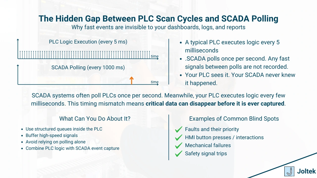
If an input signal changes for just a few milliseconds and returns to its normal state before the next polling cycle, that event is completely invisible to SCADA and MES systems. It existed, the PLC saw it, and it may have even acted on it, but no trace of that signal reaches the historian or operator interface.
This disconnect is one of the most common root causes of confusion during troubleshooting and one of the easiest problems to solve with better PLC-side design.
Historically, PLCs ran logic in a strictly sequential manner. Each instruction executed line by line, and the output was updated only after the entire program was evaluated. This made it relatively easy to predict timing and behavior.
However, newer PLCs are built with more powerful processors and increasingly complex architectures. Many now support asynchronous execution, meaning parts of the logic or special routines may run outside of the standard scan cycle. For example, interrupt routines can be triggered by a high-speed signal and execute immediately, regardless of what the main program is doing.
This capability brings more flexibility and performance, but it also increases complexity. Engineers must now account for multiple timing models, asynchronous behavior, and the risk of assumptions that no longer hold true. A routine may complete faster or slower than expected. Data may be updated mid-cycle. Outputs may change before all logic is evaluated.
When teams rely on outdated assumptions about PLC timing, they often create logic that is brittle, inconsistent, or prone to race conditions. Understanding the scan cycle and how it has evolved is essential for anyone working with high-performance systems, tight tolerances, or advanced diagnostics.
To truly understand the limitations and opportunities in your data pipeline, you need to look inside the PLC. Not just at the logic, but at how information is actually stored, organized, and updated. This section introduces the basic memory structure of a PLC and why the way you define and handle data matters more than most realize.
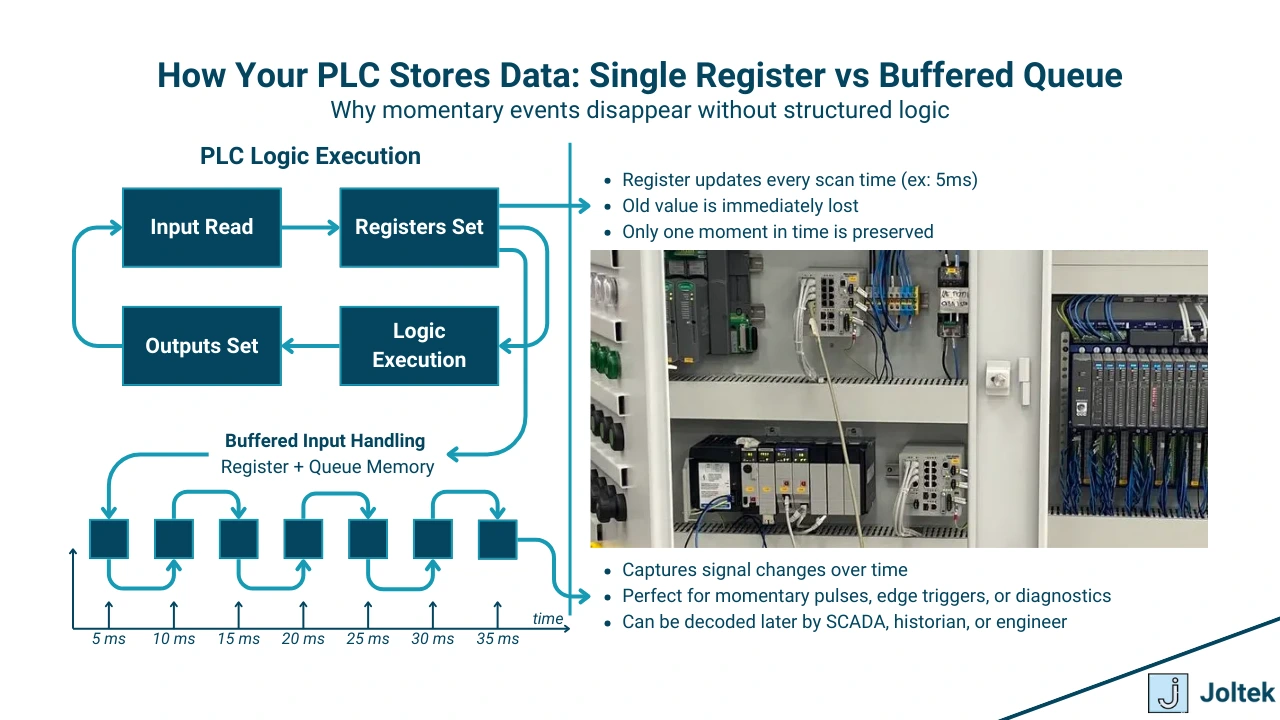
At its core, a PLC is a real-time system that works with very simple data types. Inputs and outputs are typically stored as binary values in dedicated registers. Each register holds a 0 or a 1, representing an on or off state. These are updated continuously, as fast as the PLC can scan the inputs and execute logic.
This means that most data inside a PLC is ephemeral. It exists for a few milliseconds before being overwritten. A push button may be pressed and released between two scan cycles. A sensor might briefly trigger due to vibration or machine movement, but by the time the data is polled by a higher-level system, the register already contains a new value.
The memory space inside a PLC is finite. It is optimized for speed and determinism, not for long-term storage. That is why relying on a single value to represent a signal across time can be misleading, especially when the system is running quickly.
If you treat every register as a permanent truth, you are missing the reality that PLC memory is constantly in motion.
Most early-stage PLC programs rely heavily on basic variables: individual bits for on/off signals, integers for counts, and floating-point numbers for analog values. These are easy to read and manipulate, but they carry no context.
As systems grow in size and complexity, this simplicity becomes a problem. A motor may require not just a start bit, but also feedback status, fault codes, runtime, torque demand, and other key attributes. Managing each of these as isolated variables quickly becomes unmanageable.
That is where structured data comes in.
Arrays allow you to group related values in sequence. They are ideal for tracking changes over time or storing repeating patterns. User-Defined Types (UDTs), on the other hand, let you group different kinds of values under a single logical structure. You can define a "motor" type that includes all the data points you need, then reuse that structure across your project.
Structured thinking is not just about keeping your code clean. It is about preparing your system for integration, diagnostics, analytics, and scale. Context becomes critical. When a historian or SCADA system pulls data from a structured tag, it understands what the value represents and how it relates to the rest of the system.
If your data is structured well, it can travel from the PLC to the cloud without needing constant translation. If it is not, every integration becomes a manual mapping exercise that wastes time and introduces risk.
There is a growing gap between what SCADA and MES systems expect and what PLCs are actually capable of delivering. This disconnect is often invisible until it creates a problem. And by the time that happens, critical data has already been lost.
To understand this issue, we need to look at how polling works and what it means in practice.
In many facilities, SCADA and MES platforms are configured to poll PLCs once every 1000 milliseconds. This has long been the industry norm. It is conservative enough to reduce network traffic and storage load, while still being frequent enough for basic monitoring.
But 1000 milliseconds is an eternity for a PLC.
A typical PLC scan takes around 5 milliseconds. In that same one-second polling interval, the controller may have executed its full logic loop more than 200 times. That means 200 opportunities to read inputs, evaluate logic, and update outputs. Most of that activity is completely invisible to any system polling at the one-second level.
The result is simple but damaging. A fast-changing signal may never be seen by SCADA or MES. A motor that faults and recovers within half a second might appear to have been running the entire time. A sensor that flickers due to vibration might never register as active.
This discrepancy leads to inaccurate reports, misleading trends, and hours of wasted effort during troubleshooting.
In 2018, a servo-driven line experienced intermittent shutdowns that no one could explain. The motor would stop suddenly, fault out, and then restart after a reset. The operators suspected a mechanical jam. The maintenance team replaced the motor. The line kept failing.
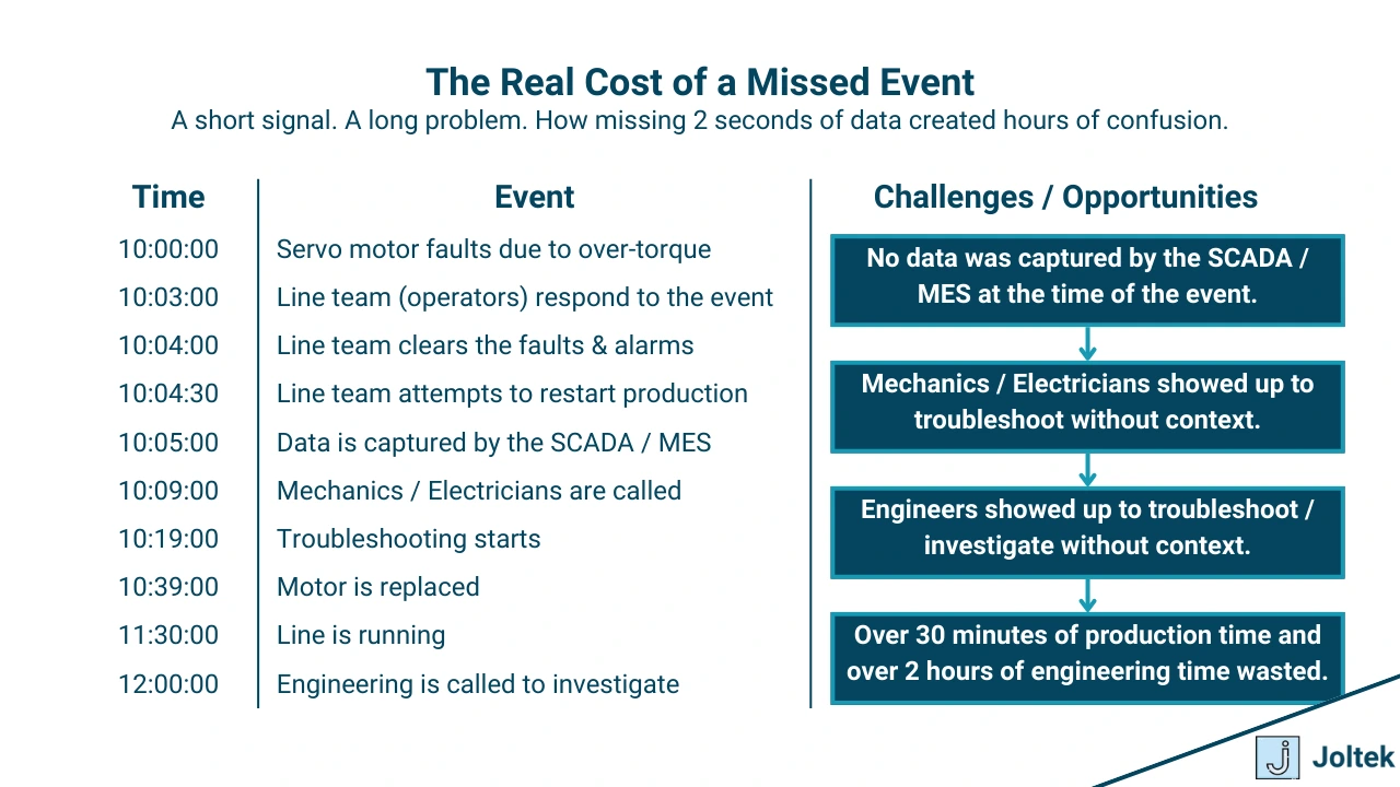
When engineering reviewed the SCADA data, there was no fault event recorded. Everything appeared normal. The system had been configured to pull data from the drive every five minutes. The only data captured was a default "over torque" code from the PLC fault register at 10:00 AM.
What no one saw was the lead-up to the fault. Current draw, speed fluctuations, and voltage spikes were all missed. By the time anyone looked at the data, the PLC had already cleared the registers. The SCADA system had already overwritten its snapshot. And the opportunity to diagnose the root cause was lost.
This scenario is not uncommon. A polling interval that works fine for a tank level or a temperature reading can be completely useless for detecting fast electrical faults, quick mechanical trips, or short-lived process conditions.
When data is missing, you cannot trust your history. And when you cannot trust your history, you cannot improve the process.
As PLC applications grow more connected and data-driven, traditional control logic is no longer enough. Engineers are being asked to design systems that not only run machines but also produce clean, usable data for a variety of downstream applications.
Meeting that challenge requires a shift in mindset.
It is not just about writing logic that works. It is about writing logic that reveals what happened, when it happened, and why.
Most PLC inputs are stored as single, real-time values. They are updated constantly and offer no memory of previous states. This design works fine when your only concern is to actuate outputs in the moment. But when a signal changes faster than your polling interval, that one value becomes a liability.
A data queue or buffer solves this problem by storing multiple time-stamped values in sequence. Think of it as a scrolling window of state changes that records what happened across time, not just in the current scan.
Instead of watching a digital input flip between zero and one, a queue can hold dozens or hundreds of those state changes. This allows you to replay events after they occurred, detect patterns, and align logic with what actually happened on the plant floor.
This approach becomes especially important for:
By implementing queues and buffers inside your PLC, you create a trail of evidence that supports diagnostics, traceability, and continuous improvement.

In traditional PLC programming, the focus has always been on physical control. Inputs trigger logic, outputs respond. But modern applications demand more than just deterministic behavior. They require thoughtful data design.
Software developers have long used patterns to manage data flow, reduce complexity, and ensure maintainability. Control engineers can benefit from the same thinking.
Here are three important concepts that apply directly to PLC systems:
By borrowing these concepts, engineers can build PLC programs that are more than just reactive. They become proactive tools that deliver reliable, structured, and contextual data to SCADA, MES, and analytics platforms.
The PLC is not just a controller that executes logic. It is also the first and most important layer in your data architecture. Every value that enters your SCADA, MES, or cloud platform starts at the PLC. If that data is not captured correctly or is structured poorly, everything that follows is built on a weak foundation.
Understanding scan time, memory behavior, and how data structures work inside a PLC is critical. It allows you to design systems that are more accurate, more resilient, and more transparent.
SCADA and MES systems cannot guess what the PLC missed. They cannot recreate fast-changing events that were never stored. They can only reflect what the PLC makes available. That is why the design choices you make at the controller level have long-lasting effects across your entire operation.
Building better systems starts by thinking carefully about how data is created, captured, and passed along from the very beginning.
This first article established the foundation. You now understand how PLCs handle data internally, why scan time and memory structure matter, and how poor design at the controller level can impact everything from troubleshooting to analytics.
In the next two parts of this series, we will build on this foundation to help you create more structured, reliable, and scalable data architectures.
Explore how to go beyond basic tags and build structured, reusable logic inside the PLC. This includes practical approaches for using arrays, implementing user-defined types (UDTs), and organizing data in a way that supports long-term scale and clarity.
Understand what it takes to move data from the PLC into SCADA, MES, or cloud platforms without losing critical information. This article will cover polling strategies, buffering, edge processing, and how to architect a data pipeline that delivers both performance and insight.

