
I released a recent newsletter article focused on context in manufacturing and industrial automation data. As expected, a lot of interesting comments were made on the post and directly messaged to me.
Read on LinkedIn: The Foundation Every Manufacturing System Depends On
One of the comments, in different forms, was around leveraging AI to add context to the data stored at the PLC / control system level. Although I agree that the thought is interesting; I want to dive deeper as to why this is complex, explain the challenges at this layer, and hopefully provide additional detail to those working with industrial data as to what they can expect to need to accomplish as they seek to add context for further data processing.
It is generally understood and agreed upon that industrial data allows for better understanding of the process and adds value beyond controlling machines. The main use cases being effective troubleshooting, bottleneck elimination, and investment prioritization based on KPIs.
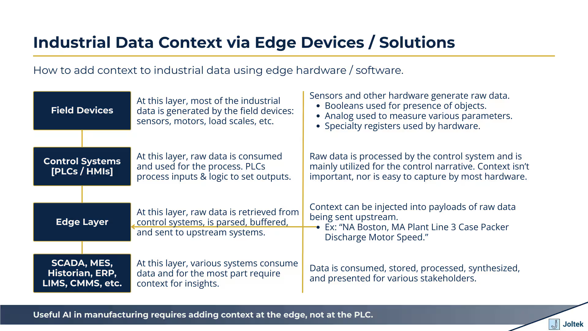
Key data is captured at the plant floor via field devices and is further enhanced as it travels up the stack via other information (ex: time, SKU, product recipes / batch, etc.) which may come from MES, ERP, and closely related applications.
The information that is generated at the plant floor is well understood by individuals that designed and work with the system. They’re intimately familiar with the signals based on their knowledge of the process, key engineering drawings, and the programs that run the systems (PLCs / HMIs).
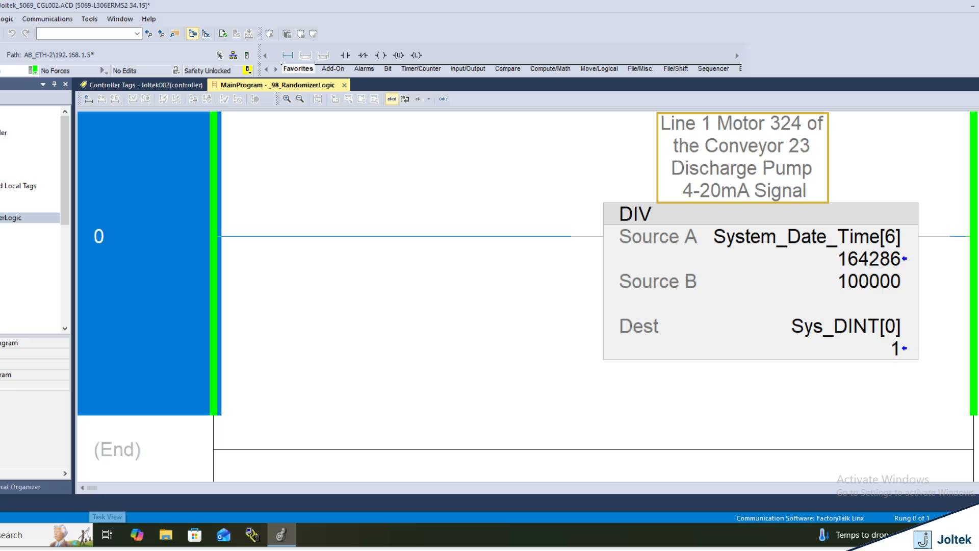
The information above, as it travels to the SCADA, MES, ERP, and closely related layers is difficult to understand for those that don’t intimately know the operation of the process. While a 4-20mA signal coming in to the PLC on input 3 is known by the plant team to be tied to the Line 3 Pump M234; the data scientist which receives the data is going to struggle to make the same connection based on the signal alone. This is a problem as the data collected in an unstructured manner doesn’t yield any results.
PLCs are optimized for controlling a process. The hardware was designed to capture inputs, process their state, and set outputs 24/7/365 for many decades. Most modern PLCs come with various tradeoffs as a result of the above. As discussed in the previous section, context is added in “human readable” format or a string. PLCs are capable of string storage, and manipulation. However, they’re not designed for that task. Let’s look at a few details and options.

In Figure 1, we observe a basic array construct of 100 DINTs within a CompactLogix PLC running v34.15 of Studio 5000 from Rockwell Automation. The array of tags is identified via a typical array structure which is labeled Sys_DINT[0], Sys_DINT[1], and so on. We also notice that the Value of each DINT is shown in the Value column, we have a data type of each element (DINT), and we have a “Description” column.
A similar data structure can be created of various other constructs - BOOL, INT, etc. It’s also possible to create an array of “specialty” data types used within the software; this includes timers, counters, FIFO elements, etc.
As one would expect, these elements can be used to create PLC logic using instructions within specific routines.
So where’s the problem?
Well, the programmer that creates the logic will know how to build a structure that will accurately follow a control narrative of a system. They’ll know which inputs / outputs are tied where as they would have reviewed electrical schematics, gone through a VAT / FAT, and understood the process that the machine is looking to accomplish.
There would be absolutely no context to this array of DINTs despite them being completely usable within this PLC program.
I’ve yet to encounter a technical problem worth solving that has a single solution. With everything we discuss below, it’s important to keep in mind that there are trade-offs or advantages / disadvantages to each one.
As mentioned above, context is typically captured as a “description” of the tag / value which contains the data. PLC programmers have access to certain string elements that can add context.
Let’s explore the first option - Naming Tags
As a PLC programmer, I can choose to name my tags. In the example above, we had an array which results in the same name with a reference pointer. You can approach this differently and create separate tags for every DINT. Here’s an example:

As you can see in the figure above, we’ve created 3 tags on the same PLC named “Line6Pump1DischargeOfTank3,” “Line6Pump1DischargeOfTank3,” and “Line6Pump1DischargeOfTank3.”
You might be able to spot a few problems with this convention, but let’s take it a step further. The first obvious issue is that we’re out of characters for naming the tag. The next issue is that the program which has thousands of I/O points will be very difficult to scale or replicate. The last obvious issue I see is that there’s no simple way of making changes to such a program without significant foresight.
In this case, tag aliasing might actually be a viable option so that we’d re-reference a value should we make modifications.
The less obvious challenge of this approach is data encapsulation. In the world of Rockwell Automation, it’s common to perform tag manipulation and passing via arrays. These constructs are important in other languages as well, but in this case they’re vital to the general operation of nearly every machine. It’s possible to find workarounds, but it’s going to be very difficult to check multiple separate tags for ON / OFF, it’s going to be difficult to produce / consume such a set of tags, it’s going to be difficult to manipulate data this way via COP or MOV commands.
The last point, is that there’s yet another advantage of using arrays! For example, an single BOOL will occupy 32 bits of data despite carrying only 1 bit of information! An array of 32 BOOLS will also occupy 32 bits of data! Which one makes for more efficient programming?
I’m a big supporter of documenting code and as of version 20 of RSLogix / Studio 5000 all of the descriptions / comments are stored on the PLC. I believe that this approach of documenting code is better than by aliasing tags to the names of the device they belong to. It’s important to note that for smaller machines I’ve found tag aliasing quite useful.

In the two figures above, you’ll notice that we’ve added a complete description of the specific register under the “Description” column. You’ll also notice that the same description will conveniently display above the tag as it is used in ladder logic routines.
So what’s the issue? Can’t we just pass the description of the tag to the server over any industrial protocol and decipher the context based on what the programmer has left?
It’s a good thought, but in reality it’s not that simple.Tag names and their values aren’t directly tied to the description outside of the visual table in RSLogix / Studio 5000. This typically means that the description isn’t going to be transferred to any other device regardless of the protocol used! The name and value will be passed; not the description.
Aren’t there ways to get around this limitation?
There are! The descriptions are stored in the files generated & saved from the PLC. This means that a text parser can and does extract the descriptions from each tag.

The figure above is a L5X file which is in XML format and displays the information about the tag. To the point above, it’s possible to extract context from the specific tag given this file and proper labeling of tags.
I’ve spent numerous years working as a “field deployed engineer” extracting data from various assets for different manufacturers. The task of adding context to a machine is rarely smooth. You’re bound to find old equipment, undocumented equipment, equipment that needs to be connected to using various protocols, and all sorts of other issues. A better approach was needed.
What’s the definition of an edge device?
Well, without going on a tangent, the goal of an edge device is to be close enough to the PLC so that there’s no data loss, but to be separated enough so that there’s no impact on general production and added capability which isn’t available on the PLC. There’s no further formal definition of which capabilities, which OS, and which platforms, or the proximity to the device an edge device can carry.
In a practical sense, an edge device can be another PLC, an IPC, a desktop computer, or even a local rack server.
This brings me to the main point of this post which is that an edge device is one of the best places to “inject context” into industrial data. An edge device is close to the plant floor which typically means that it’s sitting on the OT side. It’s almost always connected in “real time” to the control systems, and it’s usually operating via a higher level OS than the control system: Windows or Linux. The compute and storage capabilities of an edge device are also much cheaper than the ones of the controller and can be scaled much easier based on the needs of the application.
Well, the technical “how” depends on the OS, the platform, and the application / solution you’re using. In general, context can be appended to an MQTT or OPC payload and sent or broadcasted to the broker / server. This can be accomplished via various solutions available on the market.
Edge solutions are highly underestimated in my opinion. From my experience, unless you’ve worked with large amounts of industrial data, it’s hard to appreciate the combination of traditional control systems with a separate solution running applications on Windows / Linux.
For small systems, it’s perfectly acceptable to use the PLC / HMI for some of these tools; there’s no need for high speed data passthrough, data buffering, and / or compression and presentation. As the application scales to lines, departments, and multi-site, it’s very difficult to process everything on the control system (PLC). Your teams may experience increase downtime, expensive integration costs, and have a hard time delivering the data you’re looking for.
The figure above demonstrates a logical diagram which
The idea of AI aiding in industrial data is something many are exploring. The thought of being able to shorten the time to deployment of applications that collect, process, and present meaningful insights from the plant floor is extremely interesting for many stakeholders. However, it’s important to understand some of the nuances of manufacturing control systems as opposed to a software application and how they create constraints for the current state of AI.
My opinion is that if you’re attempting to build anything in this space, you need to be looking into the following:
1. Understand the capabilities and limitations of the control system you’re working with. They aren’t all made the same; some are highly restrictive with their own IDEs while others run a Linux or Windows distribution and are much more open.
2. Understand and be able to ingest various industrial documentation which includes drawings, schematics, P&IDs, manuals / datasheets, etc. By knowing the physical layout of the equipment your model is much more likely to understand context.
3. Understand how and where it’s best to add context in your specific use case. There are multiple approaches that can get you there each one with different constraints and requirements.
4. Understand the flow of data from the plant floor to Edge, to SCADA, MES, Historians, cloud, etc.
When it comes to industrial data, context is extremely important. Highly specialized engineers close to the plant floor have the best visibility and understanding of the system thus being able to add the most context to most data created in the field. Control systems (PLCs / HMIs) aren’t great at processing context for various reasons. They can store descriptions and comments, but aren’t natively capable of passing that information via commonly used protocols.
To best leverage AI in its current form it’s critical to understand some of the nuances we’ve discussed, to feed the models with the right context, and to trace the data from inception to consumption / presentation.
Noe we can all implement UNS correctly!

