
EtherNet/IP, CIP and Stratix: The Rockwell Network Layer
Stratix Switches and Plant Network Segmentation
Stratix switch selection: when a non-Rockwell switch is the better answer, the features worth using, and how to segment a plant network the way it runs.
Choosing a Stratix switch is the smaller of two decisions on a plant network. The first is what switch to buy; the second is how to divide the network. The second matters far more than the first and gets a fraction of the attention. This page covers both: when a Stratix switch earns its premium and when another industrial switch is the better answer, the configuration plants routinely miss, and how to segment a network in an order a plant can fund and survive.
It belongs to Networks in the Rockwell Automation cluster.
Choosing a Stratix switch, or not
Stratix is Cisco hardware and IOS with a Rockwell configuration layer that integrates with Studio 5000 and FactoryTalk.
| Model | Position |
|---|---|
| Stratix 2000 | Unmanaged. Only where a managed switch genuinely is not needed, which is rarer than it is specified |
| Stratix 5700 / 5800 | Managed layer 2, the mainstream plant-floor choice. 5800 is current |
| Stratix 5400 / 5410 | Managed with higher port counts and layer 3 capability, for distribution |
| Stratix 8000 / 8300 | Earlier managed generations, widely installed |
The genuine argument for Stratix is integration, not switching. The switch appears in the Logix project as a device, its diagnostics are visible to the controls team in tools they already use, and Add-On Profiles make configuration approachable for engineers who are not network specialists. On a plant floor where IT does not own the network, that is worth real money.
The genuine argument against is cost, and that a competently configured industrial switch from another vendor does the same job for less. If your IT group owns and administers the plant network with proper tooling, the integration benefit is smaller and the price premium is harder to justify.
The question that decides it: who will administer this switch in three years? If the answer is the controls team, Stratix earns its premium. If the answer is IT with existing standards and tooling, buy what fits those standards.
Stratix switch features worth using
The managed range carries features that solve specific plant problems, documented in the Stratix managed switches manual. Not every feature is on every model, so check the manual for the model in question.
| Feature | Plant problem it solves |
|---|---|
| Add-On Profile in Logix Designer | Switch status and port diagnostics visible to the controls team in the controller project |
| SD card configuration sync | A failed switch replaced with its configuration in minutes rather than rebuilt by hand |
| DHCP persistence | A replaced device on a given port receives the same IP address, so a technician can swap it without a laptop |
| Network address translation | Identical OEM machines with identical IP schemes joined to one plant network without readdressing every machine |
| Device Level Ring and Resilient Ethernet Protocol | A cable break on a ring is survived instead of stopping the line |
| CIP Sync (Precision Time Protocol) | Time synchronisation that Integrated Motion and time stamping depend on |
| Port security and Smartports | Ports locked to their intended device, and consistent port roles across switches |
DHCP persistence and NAT are the two most underused. The first turns a device replacement into a maintenance task rather than an engineering one. The second is often the only practical way to bring a row of identical machines from one builder onto a segmented network.
Segmentation: the part that matters
Segment around how the plant actually runs, not around an idealised architecture diagram.
The reference models divide a plant into zones and conduits, with a demilitarised zone between operations and enterprise; ISA/IEC 62443 and the Rockwell and Cisco CPwE design guide both describe it. That model is correct and it is a destination, not a starting point. The starting point is usually a flat network with everything on one subnet, and moving to the model in one project is neither fundable nor safe.
The order we recommend:
1. Separate control traffic from everything else. Highest value, lowest risk. Control devices should not share a broadcast domain with office printers, guest wireless or the plant’s CCTV.
2. Separate by production area. A fault on line 3 should not be able to affect line 7. This is also what makes maintenance possible: a segment you can take down is a segment you can work on.
3. Control the boundary between operations and enterprise. A firewall, and a deliberate decision about what crosses it. This is where remote access belongs as a designed capability rather than the assortment of vendor VPNs and cellular modems most plants actually have. Joltek’s OT remote access guide covers how to get from one to the other.
4. Refine within the areas as the need appears, driven by an actual requirement.
Where segmentation goes wrong is designing it around the org chart or around a diagram in a standard, then discovering that a machine on line 3 legitimately needs to talk to a system on line 7, and the traffic ends up routed through a controller or a dual-homed PC because the segmentation did not match reality. Map the real traffic first.
Configuration that is routinely missed
- IGMP snooping enabled, and a querier present. Snooping with no querier is not a working configuration, and this specific gap causes a lot of multicast problems on networks that were believed to be configured correctly. See EtherNet/IP and CIP
- Spanning tree considered deliberately, particularly where a ring topology is in use
- Port security and unused ports disabled. An open port in a panel anyone can reach is an access path
- Default credentials changed. Still found in production more often than anyone would like
- A saved, backed-up configuration for every switch. A managed switch nobody can restore is an unmanaged switch with extra steps. FactoryTalk AssetCentre can include Stratix switches in its scheduled backups
- Documented port assignments. What is on which port, in a document that is updated
Physical layer
More faults originate here than anywhere else in the network, and they are the least glamorous:
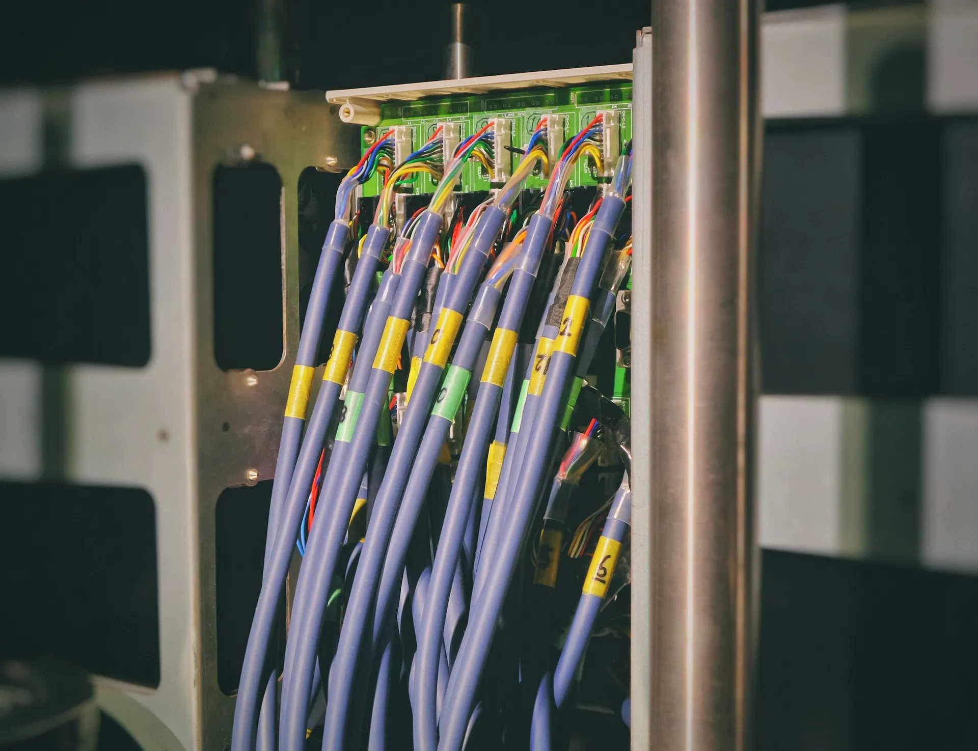
- Connectors terminated in the field without the right tooling, particularly on ruggedised connector types
- Cable routed alongside drive power cable, which is a noise coupling problem that presents as intermittent packet loss
- Bend radius violated in a tray or a panel duct
- Copper runs beyond 100 metres, discovered after the fact
- No labelling, so tracing a link means following it by hand
A network audit that does not include walking the physical layer has not audited the network.
A worked example (illustrative)
An illustrative scenario, not a description of any one plant.
A plant has six identical filling machines from one builder, each shipped with the same internal IP scheme, so they were bridged onto the plant network with unmanaged switches and a dual-homed PC for data collection. The plan: each machine gets a managed switch that translates its internal addresses to a unique plant-side range, so no machine is readdressed; the six machines move onto a filling-area segment with IGMP snooping and a querier on the distribution switch; the dual-homed PC is retired in favour of a data path through the industrial zone; and each switch’s configuration is saved and its port map documented. Which switch brand does it is decided by one question: whether controls or IT will be on call for it.
What we do
We map the network as it actually is, including the parts nobody documented, and design segmentation against how production really runs. We specify switches on who will administer them, configure IGMP and VLANs properly, and validate under production load rather than on a quiet network. Where a plant has a flat network and no budget for a full redesign, we sequence the segmentation so the highest-value separation happens first. That work usually starts as an OT network assessment; our article on segmenting a brownfield OT network covers the approach in more depth.
Related: EtherNet/IP and CIP Explained · Networks and Communications · Rockwell Automation hub
Frequently asked questions
What is a Stratix switch?
Stratix is Rockwell Automation's industrial Ethernet switch line. The managed models are built on Cisco hardware and IOS, with a Rockwell layer that lets the switch be configured and monitored from Studio 5000 Logix Designer through an Add-On Profile. The range runs from the unmanaged Stratix 2000 through managed layer 2 access switches to layer 3 distribution switches.
Is a Stratix switch better than another industrial managed switch?
Not in switching performance. Its advantage is integration: the switch appears in the Logix project, its diagnostics are visible to the controls team in tools they already use, and features such as DHCP persistence and Device Level Ring are set up from familiar software. Where IT owns the plant network with its own tooling and standards, a switch that fits those standards is often the better buy.
How should a plant network be segmented?
Around how the plant runs, in steps. First separate control traffic from office, camera and guest traffic. Then give each production line or area its own segment so a fault on one cannot reach another. Then put a firewall with deliberate rules between operations and the enterprise. Refine further only where a real requirement appears. Map the actual traffic before drawing any boundary.
What is IGMP snooping and why does it need a querier?
IGMP snooping lets a switch forward multicast only to ports whose devices asked for it, instead of flooding every port. It learns membership by listening to the reports devices send in answer to queries. If nothing on the VLAN acts as querier, those reports stop and snooping cannot keep its table current. Snooping without a querier is not a working configuration.
How do you back up a Stratix switch configuration?
Save the running configuration and store it off the switch with the rest of the plant's backups. Several managed Stratix models also hold their configuration on an SD card that can be synchronised from Device Manager or Logix Designer, which speeds up a replacement. FactoryTalk AssetCentre can include Stratix switches in scheduled backups. Test a restore on a spare switch.
References and further reading
- Stratix Managed Switches User Manual (1783-UM007) · Rockwell AutomationStratix 5400, 5410, 5700, 8000 and 8300: Add-On Profile, SD card, DHCP persistence, NAT, port security, DLR and REP.
- Ethernet Design Considerations Reference Manual (ENET-RM002) · Rockwell AutomationManaged versus unmanaged switches, IGMP snooping and querier, spanning tree.
- Converged Plantwide Ethernet (CPwE) Design and Implementation Guide (ENET-TD001) · Rockwell Automation and CiscoCell/area zones, the industrial zone and the boundary to the enterprise.
- ISA/IEC 62443 Series of Standards · ISA
- Industrial Network Products · Rockwell Automation