
Case study
Stabilizing an OEM-Built Converting Line on a Mixed Omron and Rockwell Control Architecture
Stabilizing three OEM machines on a foreign control platform, and what it produced: the line's best OEE in six months and an extended engagement.
- Sector
- Packaging and converting
- Client
- Confidential
- Read
- 26 min
- 2 weeks to 3 monthsEngagement extended by the client, with Joltek named as the on-site consultant
- Best in 6 monthsLine OEE for the period, against the site's own preceding six months
- 0Production stops required to deploy the drive current telemetry
- 18 AOutput current captured at the trip, against a 9.3 A motor nameplate
- 5.72 AOverload restriction found on the drive, against a 13.80 A factory default
- 48 hRolling hourly production record built into the controller
Technologies Omron NJ / Sysmac StudioOmron NA HMIOmron MX2 invertersEtherCAT / CoECompactLogix 5380 GuardLogixStudio 5000EtherNet/IP and CIPNAT (1783-NATR)
Executive Summary
A mid-market packaging manufacturer engaged Joltek to provide hands-on technical leadership on a spooling and rewinding line feeding downstream cartoning equipment. The machines were supplied by an original equipment manufacturer (OEM) and run on Omron Sysmac machine controllers with NA-series human-machine interfaces (HMIs). The downstream cartoner runs on a Rockwell CompactLogix safety controller. The site engineering team is Rockwell-native, no source projects were available for the HMIs, the programming environment was running on a trial license, and each machine sat behind its own network address translation appliance with no direct path between controllers.
Against that backdrop the client had four concrete problems. A rewinder press-roll drive kept tripping on several different fault codes. There was no visibility into drive load anywhere in the control system. There was no way to coordinate spooler speed with the state of the downstream equipment. And there were no production statistics on the operator interface.
| Problem | What we did | Outcome |
|---|---|---|
| A press-roll drive tripping on several different fault codes | Read the drive’s trip history and the motor nameplate before touching any protection parameter | A mechanical cause identified with evidence: 18 A at the trip against a 9.3 A nameplate. Recommendation: do not raise the limits; inspect the roll and gearbox |
| No visibility into drive load | An acyclic SDO read of output current on a one-second timer, deployed by online editing | Output current in the controller once per second, with zero production stops |
| No coordination between spooler speed and the downstream equipment | Explicit CIP messaging from the CompactLogix across both address-translation boundaries, plus enable-gated, one-shot slowdown and recovery logic | Data exchanged at roughly 200 ms with comms-fault detection; slowdown and recovery built on the first machine, replication to the other two remaining |
| No production statistics on the operator interface | Clock-aligned hourly logging in the controller | A 48-hour rolling record of average running speed and running minutes per hour on the operator screen |
| An HMI application that existed only on the panel, on a trial-licensed toolset | Upload-only synchronisation and a combined controller-plus-HMI project; the site engineer coached on Omron conventions | HMI work possible again; a licensed installation recommended before commissioning |
Over an intensive engagement we root-caused the drive trips from the drive’s own trip history rather than by adjusting parameters, instrumented output current into the controller without stopping production, built clock-aligned hourly production logging, designed and implemented a controller-to-controller data exchange across two address-translation boundaries, developed downstream-aware speed management, and recovered an HMI application that existed only on the panel. Throughout, the site engineer was coached on the differences between Rockwell and Omron conventions so the work can be maintained internally.
The engagement also surfaced structural risks in the installed base: undocumented parameter changes on drives, missing OEM source projects, HMI firmware drifting from the engineering toolset, trial licensing, and a network design in which machine-to-machine communication has to cross two translation boundaries.
The site’s directors recognised the change on the line and reported overall equipment effectiveness (OEE) for the period ahead of any month in the preceding six. The engagement was extended from two weeks to three months, with Joltek asked for specifically as the on-site consultant.
Impact Highlights
- A recurring drive trip was traced to a mechanical cause with evidence, and the recommendation was explicitly not to change the protection settings.
- Output current was captured at 18 A at the moment of trip against a 9.3 A motor nameplate, roughly 194 percent of full-load current.
- The drive’s overload restriction had been reduced to 5.72 A against a 13.80 A factory default by an unrecorded prior party, which was itself the most informative fact on the machine.
- Drive current telemetry was deployed into a running production line with zero production stops.
- A 48-hour rolling record of average running speed and running minutes per clock hour now sits in the controller and on the operator screen.
- Two controller platforms now exchange data at roughly 200 ms across two address-translation boundaries, with comms-fault detection gating any logic that consumes it.
- The site reported line OEE for the period ahead of any month in the preceding six.
- The client extended the engagement from two weeks to three months and asked for Joltek by name as the on-site consultant.
Line and Engagement Context
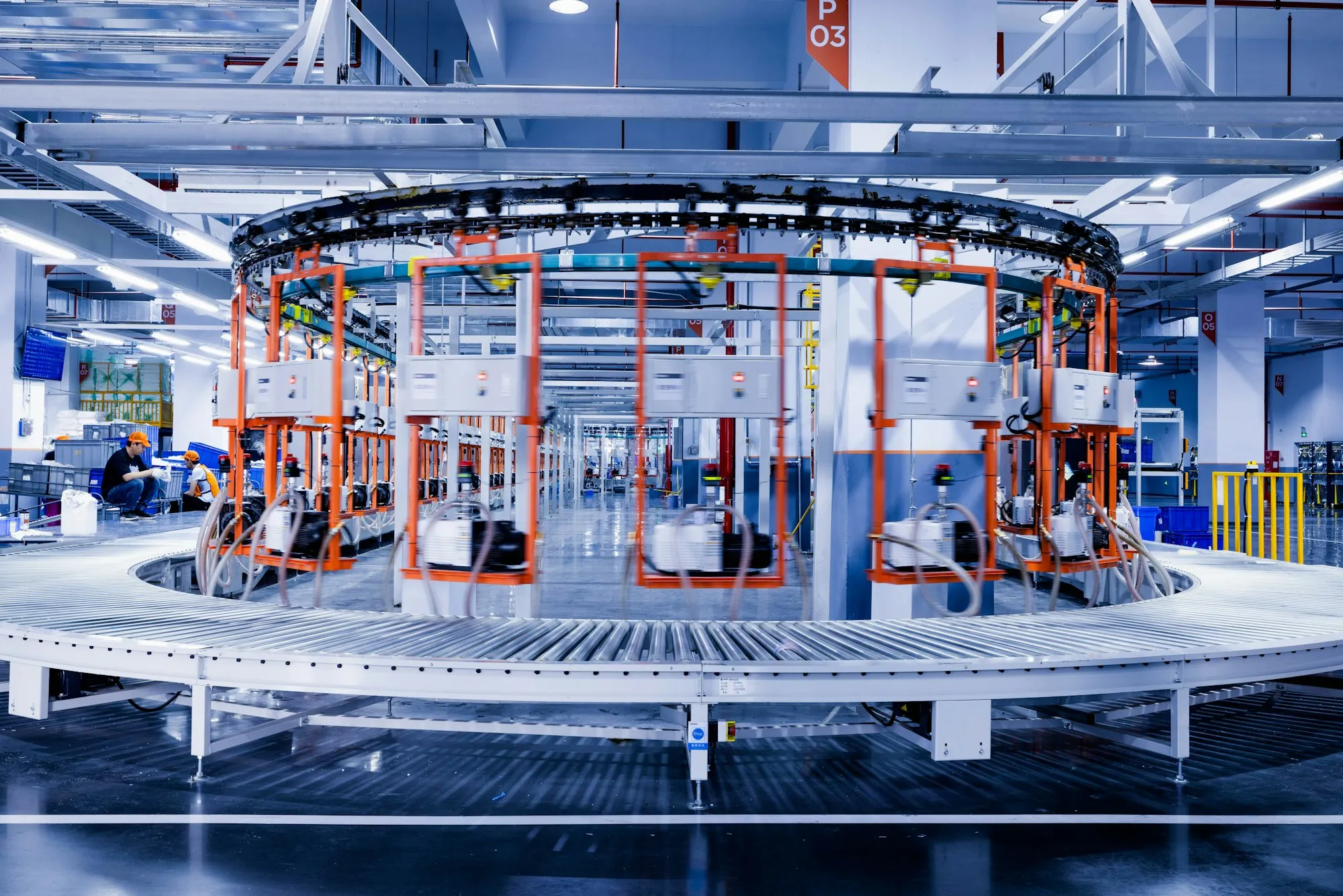
The line consists of three functionally identical spooling and rewinding machines, each built by the same machine builder, feeding a downstream cartoning and case-packing cell. Each spooler is a self-contained control island:
- An Omron NJ-series machine automation controller running the machine program, with an EtherCAT network of roughly twenty nodes. Omron servo drives on the knife, fingers and tail orienters. MX2-class inverters with EtherCAT option boards on the press roll, main motor, exit belts, accumulators and unwinder arms. A web guider, and a remote input/output (I/O) coupler for cabinet I/O.
- An Omron NA5 12-inch HMI running the operator application, developed originally as part of the same Sysmac Studio project as the controller.
- A Rockwell 1783-NATR address-translation appliance presenting the controller and HMI to the plant network as public aliases while the machine itself lives on a private subnet.
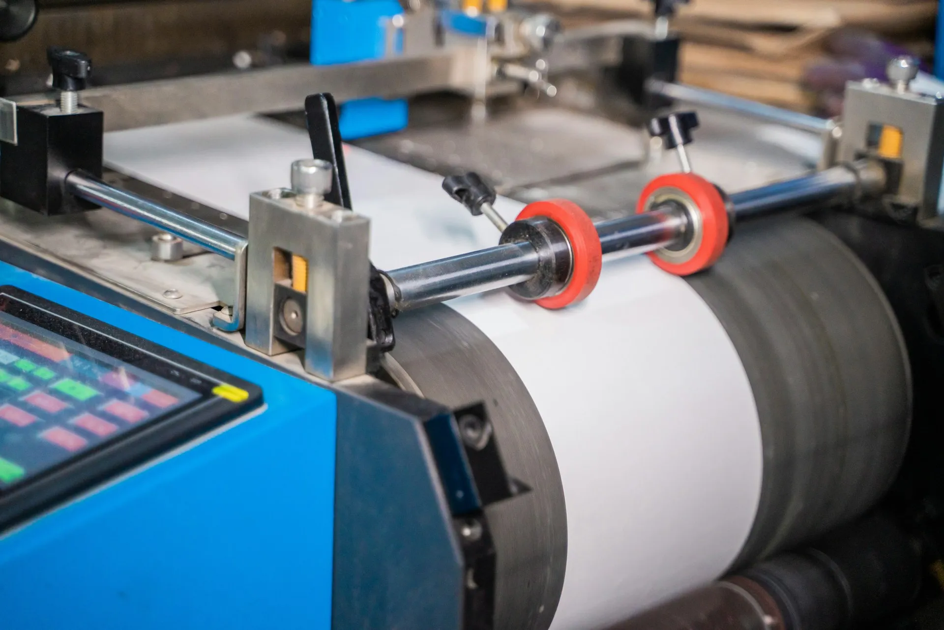
The downstream cartoner is controlled by a CompactLogix 5380 GuardLogix safety controller programmed in Studio 5000, behind its own address-translation appliance. An Ignition supervisory control and data acquisition (SCADA) platform is present at site level. The machine builder’s program base uses a structured group data model: a large array of per-subsystem structures holding constants, auxiliary values, operator pushbuttons, switches and alarm bits.
This shape is not unusual. A plant standardises on one controller platform, then buys a capable machine from a builder who standardises on another, and the machine arrives as a sealed island. Everything works until the day the plant needs to change something inside it, or needs it to talk to the equipment on either side.
The Problem and the Risks
Unplanned downtime costs the world’s 500 largest companies about 11 percent of annual revenue, up from 8 percent in 2019, according to Siemens’ True Cost of Downtime 2024. We cite that as industry context and not as a measurement of this line, because nothing in this engagement was measured that way. What this line had was a set of conditions that reliably turn into downtime later.
A drive that kept tripping, and an alarm that discarded the reason. The machine’s alarm logic latched a generic press-roll driver alarm when one bit of a drive status word stayed true for 3.2 seconds. That bit says only that the drive has tripped. It carries no reason. The drive itself stores a detailed fault history. None of it reached the operator, the maintenance team or the controller.
No load visibility anywhere. The machine builder mapped five words from each inverter into cyclic process data: speed reference, actual speed, status, command and error code. Output current, torque and thermal load were not among them, and the option board’s process-data assignment could not be edited from the engineering tool. Reading a current therefore meant walking to the drive and scrolling a keypad.
No coordination with downstream equipment. When the cartoner stopped, the spoolers kept running at speed until an operator intervened. On a web-handling machine that is an accumulation problem and a quality problem.
No production record on the operator interface. The line ran; nobody could say at what average speed, or for how many minutes of the last hour.
And underneath all four, a maintainability problem. No combined controller-plus-HMI source project existed on site. The controller program could be uploaded. The HMI application existed only on the panel. The engineering environment was a trial edition with about three weeks left on it. A Rockwell-native team was supporting an Omron line without the tools, the source, or the platform fluency to do it, and the risk that carries is not a fault code. It is the day something breaks and the only recovery path runs through a machine builder in another country.
Objectives and Success Criteria
Seven objectives were agreed before work started, and “done” was defined for each one.
| # | Objective | Success criterion |
|---|---|---|
| 1 | Determine why the press-roll drive trips | An actionable, defensible root cause supported by data from the drive, not an adjusted parameter |
| 2 | Get drive load into the controller and onto the HMI | A live current value, ideally with no production stop |
| 3 | Provide a rolling hourly production record | Average running speed and running minutes per hour, labelled by clock hour, on the operator screen |
| 4 | Establish data exchange between the Omron and Rockwell controllers | A verified path across the address-translation boundary, with fault detection |
| 5 | Implement downstream-aware slowdown and recovery | Operator can enable, disable and adjust setpoints; behaviour on disable is defined |
| 6 | Recover and stabilise the HMI project | New faceplates can be added and deployed safely |
| 7 | Leave the site team able to maintain and extend the work | Platform differences documented and coached, not just fixed |
Objective 7 is the one that changes how the other six are done. A fix that only Joltek can maintain is a liability handed to a plant, not an asset.
Baseline Assessment
Two findings from the baseline changed the shape of the engagement.
The drive’s protection had already been quietly relaxed. The press-roll drive’s overload restriction level was found at 5.72 A against a factory default of 13.80 A, roughly 41 percent of default. No record existed of who changed it or why. Read correctly, this is not a configuration error to be corrected. It is evidence that somebody had already been fighting this symptom, and it dates the problem well before the engagement.
The production boundary is sharper on this platform than the team expected. On the NJ, exactly two things are online-editable: program organization units and global variables. Data types, EtherCAT and EtherNet/IP configuration, process data object (PDO) maps and task assignments all require a PROGRAM-mode download, which stops the machine. The NA HMI has no online editing at all, and every transfer restarts the runtime and blanks the operator screen.
That single distinction determined the sequencing of the entire engagement. Every proposed change was classified as online-editable or download-required, and download-required items were collected into a planned-stop list rather than executed piecemeal.
Strategy and Design Decisions
Five decisions carried the engagement. In each case the alternative was real, and in three of them the alternative is what most people would have done.
Diagnose the drive before adjusting it. The obvious move with a nuisance-tripping drive is to raise the limit that is tripping. Instead we read the drive’s captured trip conditions and the motor nameplate before touching any protection parameter, and the data argued against a parameter change altogether. The trade-off accepted was that there is no quick fix: production stays exposed until a mechanical inspection happens.
Read the current acyclically rather than remapping the network. The cyclic process data map was fixed and could not be edited from the tool. In CANopen over EtherCAT (CoE), PDOs carry cyclic data on a map agreed at configuration time, while service data objects (SDOs) give acyclic read and write access to any object dictionary entry on demand. The drive’s monitor registers are exposed as CoE objects, so a periodic SDO read gets the value without touching the network configuration. A cyclic PDO mapping remains the preferred long-term design. It was unavailable here without a network download, and an acyclic read on a one-second interval is entirely adequate for load monitoring.
Trigger the hourly log on the real-time clock, not on an elapsed-time timer. A free-running one-hour timer is simpler and has no clock dependency. The client wanted rows labelled by clock hour and a live in-progress row, and only a clock-aligned design gives that. The dependency introduced is honest and recorded: if the controller’s real-time-clock battery fails, the hour labels will be wrong after any power cycle, although the logging itself continues.
Explicit Common Industrial Protocol (CIP) messaging rather than implicit tag data links or a SCADA bridge. This is the decision the topology forced.
| Option | Assessment | Decision |
|---|---|---|
| Implicit tag data links (cyclic Class 1 I/O) | Deterministic and logic-free once configured. But the tag-set configuration is not online-editable, and a continuous connectionless UDP I/O connection with connection state held in two separate translation appliances is the fragile case | Not selected for this topology |
| Explicit messaging (CIP Data Table Read and Write from the Rockwell side) | A connected TCP request and response traverses translation gracefully. Only one side originates. The Omron side needs only published variables. The Rockwell messaging tooling is mature. Not cyclic, and slightly more logic | Selected |
| SCADA-mediated bridge (Ignition reads one controller, writes the other) | Sidesteps translation entirely, but introduces a single point of failure, non-deterministic latency, and requires rigorous quality gating so stale values are never forwarded | Retained as fallback |
One-shot writes at the transitions, not a level-held setpoint override. The speed-command variable is shared with other logic and with the operator. Continuously rewriting it would fight any other writer and would make manual intervention impossible while downstream equipment stayed down. Commanding once at each transition and then leaving the setpoint alone respects both. The accepted trade-off is that the stored pre-slowdown speed can go stale in one specific disable-and-re-enable sequence, which is documented rather than engineered around.
Implementation
Work ran as a sequence of focused, time-bounded sessions with the site engineer at the machine and in the engineering tools, screen-sharing as work progressed. Several working rules governed how changes were made.
Verify against documentation, not memory. Where an instruction signature, an object index, a trip-code meaning or a network path format mattered, we loaded the vendor manual and searched it, or used the tool’s own autocomplete and tooltips to confirm the exact form. Several early assumptions made from memory turned out to be wrong for this platform version. Confirming before committing kept them out of the controller.
Prove the network before the logic. For the cross-boundary integration, the rule was that a public alias had to be reachable by ping from the originating side before any messaging logic was written. Messaging logic that fails because of an unreachable address is indistinguishable, from the logic’s point of view, from a bug.
Push one known value first. Every new data path, the SDO read, the array logging and the controller-to-controller exchange, was validated by pushing a single recognisable value through it and checking that it arrived unchanged, before real data was trusted. Scaling errors and byte-order mismatches are cheap to catch this way and expensive to catch any other way.
Build HMI changes offline and simulate. Because the panel cannot be edited live, all HMI work was done in the project and exercised in the simulator before any transfer was contemplated.
Back up before and after, with a naming convention that distinguishes the three machines and the controller from the HMI. And translate the paradigm: each Omron convention that differed from Rockwell practice was called out explicitly as a difference rather than as an error, so the knowledge transfers and not merely the fix.
The drive telemetry itself was built as an EC_CoESDORead call driven by a self-resetting one-second timer. The timer’s Q output, inverted, feeds its own input, producing a single-scan pulse per second. The pulse sets a latch only if the instruction is not already busy. The latch drives Execute. On Done the raw value is converted and scaled into an engineering-units variable, and the latch clears. On Error the latch also clears and the value is not used.
One detail from that build is worth publishing because it is the kind of thing that ships wrong and reads correct: the option-board manual carries separate object tables for two drive families, and the resolution of the same monitor differs between them. Output current is 0.01 A on one and 0.1 A on the other. Using the wrong table would have produced a value out by a factor of ten, in engineering units, on a screen, looking entirely plausible.
The hourly logging went through three deliberate iterations, each a response to a clarified requirement rather than a correction. A timer-driven ring buffer came first, which was simple but would have needed pointer arithmetic on the HMI and could carry no absolute time. A timer-driven shifting array replaced it, fixing the HMI mapping so row N always reads element N, at a cost of 47 array copies once an hour. The final design changed the trigger from an elapsed-time timer to a real-time-clock hour change, so index 0 is the in-progress hour, updated every scan, and the operator watches the current hour’s average and running minutes build in real time.
Challenges and How They Were Resolved
Every project has the moments that do not go to plan. These are the ones that cost time on this one.
| Challenge | Impact | Resolution |
|---|---|---|
| A program-local variable shadowing a global of the same name | Cross-reference showed zero uses of a variable that was visibly present in the logic. Hours of misdirected debugging available here | Inspect the program’s Internals table. Delete the local so the name resolves to the global, or use Externals explicitly |
| An open online-edit session blocking other editor operations | Greyed-out variable registration, Data Trace refusing to start, build errors referencing already-fixed variables | Apply or cancel the session deliberately. Cancelling discards everything in it, including global variables added earlier in the same session |
| Strict typing with no implicit promotion | A steady stream of build errors on division, bitwise AND and output-parameter assignment | Convert explicitly on every operand, match types, and use the output-assignment operator for outputs |
| HMI uploaded without source and unlinked from the controller | No variable bindings resolvable, faceplate work blocked | Upload-only synchronisation on the runtime mismatch, then a combined project built by uploading both devices into one project and linking the device reference explicitly |
| Plant power interrupted during an HMI transfer | The panel came back without a bootable application and with its settings reset | Confirm the panel reachable on the private subnet, then re-transfer a complete application from the saved project under stable power |
| A copied display object carrying an inherited scaling transformation | A displayed value silently altered by a unit conversion nobody configured | Clear the inherited transformation. Copied objects bring their behaviour properties with them |
| Fixed drive process-data map | No current, torque or thermal signal in the controller | Acyclic SDO read of the monitor objects, deployed online |
| Alarm logic reducing rich drive diagnostics to one status bit | No root cause visible to operators or maintenance | Read the trip-history registers on the drive, compare against the motor nameplate, conclude mechanical |
| Two translation boundaries between controllers | No direct path for I/O, implicit messaging fragile | One-to-one translation rules and gateways configured, explicit messaging from a single originator, gated on a successful ping |
| Three near-identical machines | Real risk of editing the wrong controller’s drive or logic | Per-machine naming on every new variable, message and backup. Confirm which machine before opening any drive parameter view |
| Engineering tool on a trial license | Weeks of runway, and a risk of being unable to transfer finished work | Flagged early. Licensed installation recommended before commissioning |
The power interruption during an HMI transfer is the one worth dwelling on. Nothing about it was anyone’s mistake, and recovery was straightforward once the panel was confirmed reachable. It reinforced two disciplines that now apply to every transfer on this line: export the project before every transfer, and treat HMI transfers as planned-stop activities where the panel’s power is secured.
Results and Impact
The drive. The decisive data came from the drive’s trip-history registers. At the moment of the overcurrent trip the drive was at 19 Hz output and 18 A output current, with the DC bus at a normal level. The motor nameplate gives 9.3 A full-load current. Normal running current observed during the engagement was about 4 A.
| Quantity | Value | Interpretation |
|---|---|---|
| Motor full-load current | 9.3 A | Nameplate, at the supply voltage in use |
| Typical running current | About 4 A | Roughly 43 percent of full load. Lightly loaded when healthy |
| Current at trip | 18 A | Roughly 194 percent of full load. A genuine, large demand, not a marginal setting |
| Frequency at trip | 19 Hz | Low speed on a two-pole motor, which is where low-speed overload protection lives |
| Overload restriction level | 5.72 A | Factory default 13.80 A. Reduced by an unrecorded prior party |
A motor running at under half its rated current in normal operation does not reach nearly twice rated current because a protection limit is set conservatively. Four different protection functions tripping on the same roll, thermal, low-speed and overcurrent, are the drive reporting one condition in several languages: the roll is intermittently very hard to turn.
The recommendation was explicit. Lock out the drive, turn the roll and gearbox by hand, and inspect bearings, the nip setting, the coupling and the gearbox for drag, damage or product wrap. Do not raise the thermal or overload limits. Raising them would remove the protection while the mechanical problem continued, converting a recoverable drive trip into a motor or gearbox failure.
The instrumentation. Output current now updates once per second in a controller variable that can be watched, trended in Data Trace, displayed on the HMI, or used in logic. It was deployed by online editing with no production stop, the one instrumentation improvement in the engagement that did not need a maintenance window. The same pattern extends to the thermal-load and torque objects.
The production record. A clock-aligned 48-hour rolling record of average running speed and running minutes per hour now sits in the controller, with hour labels, a live in-progress row, mirrored into the machine builder’s own HMI data structure so the existing screen conventions bind to it, and a one-shot clear.
The integration. A verified network path exists across both translation boundaries, with a Rockwell-originated read and write against published Omron arrays, interlocked so the two messages never overlap and with their error bits combined into a communications-fault flag that gates any logic consuming the data. Downstream-aware slowdown and recovery logic is built, enable-gated and one-shot, with the disable behaviour agreed and the open verification items handed over.
What the site measured. The line’s directors recognised the change on the floor, and overall equipment effectiveness for the period came in ahead of any month in the preceding six. That figure is the site’s own, from the site’s own reporting, and we publish it as they reported it rather than reconstructing it. We are also careful about what it does and does not prove: several things changed on that line at once, the mechanical inspection behind the drive trips is a maintenance action that sits outside this engagement, and no controlled comparison was run. What can be said is that the site’s own numbers moved in the right direction over a period in which this work was the notable variable, and that the people who own those numbers attributed the change to it.
What followed. The engagement was extended from two weeks to three months, and Joltek was asked for by name as the on-site consultant rather than as a supplier of hours. That is the outcome we treat as the real one. A plant that has just watched someone work on its equipment has better information about the value of that work than any metric does, and what it does next with the contract is the least ambiguous signal available.
What was not completed. The physical inspection of the press roll and gearbox is a maintenance action outside the engagement’s remit, and it is the action on which the drive problem actually turns. Replication of the exchange and slowdown logic to the other two spoolers remains, with the first machine as the template. The HMI runtime-version strategy is an open decision ahead of the next transfer. Formatted hour-range labels on the HMI were dropped in favour of the raw hour value after the expression language did not behave as assumed, and that is recorded as a deliberate simplification rather than a completed feature.
Lessons Learned
The drive knows why it tripped. The controller usually does not. When an alarm is derived from a single status bit, the diagnosis lives in the drive’s trip history. Reading those registers before touching any parameter is what turned a parameter-tuning exercise into a mechanical finding.
A relaxed protection setting is a clue, not a fix. The lowered overload restriction was the most informative single fact on the drive. It showed the problem was old and that someone had already tried the wrong remedy.
Classify every change by whether it needs a stop. Knowing that program logic and globals are live-editable while configuration is not shaped the entire engagement, and the current-monitoring feature shipped live precisely because it was designed to stay inside that boundary.
Prove the network with a ping before writing a single message. Communications logic cannot tell an unreachable address from a bug.
Push one known value through every new path. Scaling and byte-order errors are cheap to find this way and expensive to find any other way. The two-tables-one-monitor detail in the drive manual would have been a tenfold error on an operator screen.
On an unfamiliar platform, confirm signatures in the tool, not from memory. Several plausible-looking instruction forms were wrong for this version. The tooltip was the authority every time.
Near-identical machines need per-machine naming from the first variable. The one address mix-up between two spoolers was caught, and it was caught only because the naming convention made it visible.
Verify what a name means before acting on it. A program section named after a software product triggered a safety caution that turned out to be unnecessary. The caution was correct given the name. The name was the problem.
And the structural one. The absence of a combined controller-and-HMI source project cost days across this engagement and remains the single largest maintainability gap on the line. Machine builders hand over what the purchase order asked for. If the purchase order does not require editable source for controllers and HMIs, a parameter export for every drive, and a record of any protection setting changed from default, the plant finds out what it did not ask for on the day it needs it. That belongs in a site standard for OEM handover, and it is cheaper to write than any of the work described above.
The work that was valued was not the code. Every deliverable here was small. A one-second read, three rungs of structured text, two messages, three arrays. What the directors bought, and what they extended, was somebody deciding which of those to build, which to refuse, what needed a stop and what did not, and what the network should look like in three years. Joltek’s role throughout was accountable technical lead: independent of the machine builder, the drive vendor and the network appliance vendor, making and explaining the calls on what to change, what not to change and what to do first, and leaving the client’s own team more capable than it started.
This engagement sits across Joltek’s work in systems integration and systems modernization and risk management. The transport decision in the integration workstream is the argument set out at greater length on EtherNet/IP and CIP, and the case for routed cell subnets over per-machine address translation is developed on Stratix and network segmentation and in the OT networks overview.
References and further reading
- MX2 Inverter User's Manual (I570) · OmronTrip codes, the trip-history monitors and the overload restriction parameters.
- Inverter MX2/RX Series EtherCAT Communication Unit User's Manual (I574) · OmronThe CoE object tables for the drive monitors, including the two resolutions for the same value.
- NJ/NX-series Instructions Reference Manual (W502) · Omron
- EtherCAT Technology · EtherCAT Technology GroupHow cyclic PDO and acyclic SDO communication differ.
- EtherCAT Device Protocol poster · EtherCAT Technology Group
- Configurable NAT Router User Manual (1783-UM008) · Rockwell Automation
- 1783-NATR · Rockwell Automation
- EtherNet/IP · ODVAThe network and CIP messaging used for the controller-to-controller exchange.
- The True Cost of Downtime 2024 · Siemens