
Insights
OT Network Architecture for Small and Medium Manufacturers: A Design Guide for IT Teams
OT network architecture for small and medium manufacturers, explained for IT teams: switching, VLANs, machine networks, legacy fieldbus and how it grows.

Table of contents
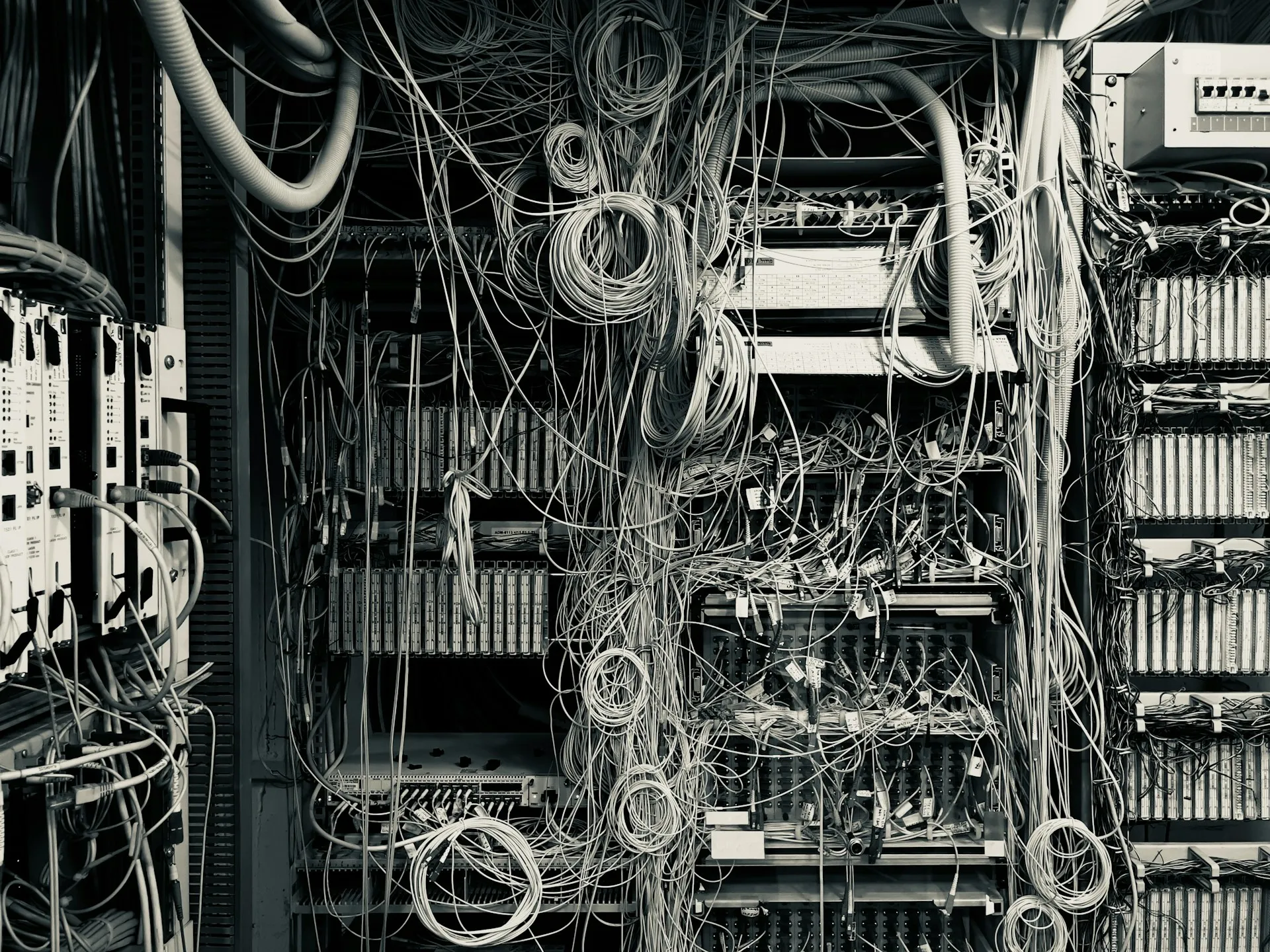
Most small and medium plants run a flat OT network, and nobody designed it that way. It grew one machine at a time. An integrator dropped a switch into a panel, an OEM shipped a skid already addressed on 192.168.1.x, and someone gave the historian a second network card. The network kept working until the day it didn’t. Now IT is being asked to own it.
Here is the short answer. For a plant of 50 to 500 devices, a sound OT network architecture is a managed switched backbone, a handful of VLANs by area, one Layer 3 point that routes between them and holds the rules, a firewall between the plant and the office, and small private networks behind PLCs, so that drive and I/O traffic stays at the machine. You build it in stages, not all at once.
This guide is written for the IT professional who runs the corporate network and has been handed the plant floor. It takes a position that differs from most of what ranks for this topic. Keep it as simple as the plant allows. Unmanaged switches still have a place, inside a machine. Legacy fieldbus networks are part of the design, not a footnote. And the right design for a 60-device plant is the wrong design for a 400-device one. It is not black or white.
By the end, you should be able to sketch the target design for your own plant and the order in which to reach it.
What is OT network architecture, and how is it different from the IT network you already run?
OT network architecture is the arrangement of switches, segments, routing and boundaries that carries control traffic between PLCs, I/O, drives, HMIs and supervisory systems. It uses the same Ethernet, VLAN and IP concepts as your IT network. What differs is the priority order: availability and timing first, integrity second, confidentiality third. And a mistake stops production rather than slowing email.
The vocabulary transfers. A managed industrial switch speaks 802.1Q, runs spanning tree and has a CLI or web interface you will recognise. The consequences do not transfer. On an office network, a two-second outage while spanning tree reconverges is invisible. On a plant network, it can drop every I/O connection on a line.
The reason is cyclic traffic. A PLC exchanges data with its I/O, drives and other controllers on a fixed interval, the requested packet interval (RPI), often in the tens of milliseconds. It does not retry politely. In a Rockwell Logix system, an I/O connection times out after four times the RPI, with a 100 ms minimum, according to Rockwell’s Ethernet Reference Manual. When the connection drops, the controller faults the module, and outputs go to their configured safe state. A conveyor stops. A filler stops mid-cycle. Someone has to clear it.
| Dimension | IT network | OT network |
|---|---|---|
| Priority order | Confidentiality, integrity, availability | Availability and timing, integrity, confidentiality |
| Dominant traffic | Request and response, bursty, TCP | Cyclic I/O at fixed intervals, much of it UDP |
| Tolerance for interruption | Seconds are usually invisible | Tens of milliseconds can fault a line |
| Asset life | Three to five years | Fifteen to twenty-five years is common |
| Patch windows | Scheduled, frequent | Planned shutdowns, sometimes once or twice a year |
| Multicast | Rare | Used by some control traffic and time synchronisation |
| Who may change it | IT under change control | Often the integrator, the OEM and maintenance, each without telling the others |
| What an outage costs | Productivity | Scrap, missed shipments, safety and restart time |
The same switch and VLAN skills apply on the plant floor. The change control, the maintenance windows and the definition of “down” are different, and the design has to account for them.
The hardware an IT person meets on the plant floor
On a plant floor you will meet familiar devices in unfamiliar roles: managed and unmanaged industrial switches inside control panels, drives and I/O with a two-port switch built in, PLCs with two Ethernet ports, NAT devices in front of machines, linking devices that bridge old fieldbus networks to Ethernet, and industrial firewalls. Each one is a design decision someone made, often a machine builder.
| Device | What it does | Where it sits | Nearest IT equivalent |
|---|---|---|---|
| Managed industrial Ethernet switch | VLANs, IGMP snooping, ring protocols, diagnostics | Area and line panels, backbone | Access switch, hardened |
| Unmanaged switch | Forwards frames, nothing else | Inside machines and small panels | Desktop switch |
| Embedded two-port switch | Lets drives and I/O daisy-chain or form a ring | Inside the device itself | None |
| Layer 3 core or distribution switch | Routes between plant VLANs, holds access lists | Main network room or a central panel | Core switch |
| Industrial firewall | Enforces the plant boundary and sometimes machine boundaries | Between plant and enterprise, in front of critical cells | Perimeter or internal firewall |
| NAT device | Translates a machine’s private addresses to plant addresses | At the edge of a machine | NAT router |
| PLC Ethernet module or dual-port controller | Connects the controller to one or two networks | In the controller rack | A server with two network cards |
| Linking device or protocol gateway | Bridges DeviceNet, ControlNet, PROFIBUS or Modbus RTU to Ethernet | In the panel beside the legacy network | Protocol translator |
| Remote I/O adapter | Brings field I/O back to the controller over Ethernet | In field panels around the line | None |
| Variable frequency drive | Controls a motor; often an Ethernet node with an embedded switch | Motor control centres and machine panels | None |
Plant-floor hardware is built for the panel: DIN-rail mounting, 24 VDC power, fanless cooling, extended temperature ranges and resistance to vibration and electrical noise. That is why an eight-port managed industrial switch costs several times what an office switch with more ports does. The price buys survival in a cabinet beside a 480 V drive.
The embedded two-port switch deserves a note because IT designers rarely meet it. Many drives, I/O adapters and controllers carry two Ethernet ports with a switch inside. That is what lets a machine builder daisy-chain ten devices with no external switch, or close the chain into a ring. It also means a device in the middle of a chain is part of the network infrastructure. Unplug it for maintenance and everything downstream disappears.
For a broader view of how we approach this layer, from cabling to the security boundary, see how we approach the plant network layer.
The Purdue model without the dogma: what runs where in a small plant
The Purdue model is a map of trust, not a wiring diagram. It sorts systems into levels, from sensors and actuators at Level 0 to business systems at Level 4 and above, and says traffic should only move between adjacent levels. In a small plant, Levels 0 to 2 often share a building and sometimes a switch. That works as long as the boundaries are enforced.
The model came out of Purdue University’s work on computer-integrated manufacturing and was later carried into ISA-95, the standard most MES and ERP integrations reference. You will see it on every vendor slide. What matters for a designer is the rule it implies.
| Level | What it is | Typical assets in a 200-device plant | Where it sits on the network |
|---|---|---|---|
| 0 and 1 | Sensors, actuators, field I/O, drives | Photo-eyes, valves, remote I/O, VFDs, scales | Machine or area networks, often private behind a PLC |
| 2 | Control and local supervision | PLCs, line HMIs, safety controllers | Area VLANs |
| 3 | Site operations | SCADA server, historian, MES, engineering workstations, OT domain services | A supervisory VLAN |
| DMZ | The handover point | Historian copy, patch server, remote-access gateway | A firewall leg of its own |
| 4 and 5 | Business and the outside world | ERP, email, cloud services, the internet | The enterprise network |
NIST’s guide to OT security, SP 800-82 Revision 3 (September 2023), puts the rule plainly in section 5.2.3.1. A good network architecture characterises, segments and isolates IT and OT devices. Firewall rules should only permit connections between adjacent levels, so Level 4 devices never communicate directly with Levels 2, 1 or 0. NIST also allows segments to be drawn by management authority, criticality, data flow or location, not only by level. That flexibility is what makes the model usable in a small plant.
The model gets misapplied in two directions. Some designs treat every level as its own physical network, with separate switches and a firewall between each pair, in a plant with one maintenance electrician who knows the network. Others declare the model obsolete because edge devices and cloud historians exist. For a single site, it remains the clearest way for IT and engineering to agree who may talk to whom. Draw the levels, then decide where the enforced boundaries go. In most small plants that is two places: between the plant and the office, and around each machine.
Managed vs unmanaged switches in OT: where each belongs
Managed switches belong on the backbone and anywhere traffic crosses from one area to another. Unmanaged switches are acceptable only inside a small, isolated machine network with few connections, modest update rates and no route to IT. Rockwell and ODVA, the organisation behind EtherNet/IP, both state those conditions. The skill is knowing where that boundary sits.
A managed switch buys an OT network six things it cannot get any other way:
- VLANs to divide the network by area
- IGMP snooping to contain multicast
- port diagnostics that tell you which cable is failing
- port security
- ring redundancy protocols
- port mirroring, so a monitoring tool can see the traffic
An unmanaged switch has none of them. It forwards frames and nothing else.
The vendors do not agree on how strict to be, and the difference is useful. Rockwell’s Ethernet Reference Manual (ENET-RM002, December 2019) accepts unmanaged switches in two situations:
- the application carries no I/O traffic;
- it does carry I/O, but the network is not connected to the IT network, all nodes are Rockwell devices and nothing can be overloaded with traffic.
ODVA’s infrastructure guide for EtherNet/IP is more specific. Isolated systems with 10 or fewer devices, a low number of connections and RPIs slower than 10 ms may not suffer from unwanted traffic. Applications with fast RPIs or more than a few connections should use managed switches with IGMP snooping.
Cisco and Rockwell’s Converged Plantwide Ethernet design guide goes further. It does not recommend unmanaged switches at all, and warns that teams who choose infrastructure on initial cost often find later that the cheaper, unmanaged equipment cannot scale, perform or integrate. On PROFINET, the PROFINET Design Guideline from PROFIBUS & PROFINET International limits unmanaged switches to conformance class A networks.
The technical reason is multicast. An unmanaged switch treats multicast like broadcast and sends it out of every port. Each end device then has to receive and discard traffic it never asked for. ODVA’s guide also makes a point that surprises people: splitting the devices across several unmanaged switches makes no difference to the total multicast load, because the switches forward it to each other.
| Location | Switch type | Why |
|---|---|---|
| Backbone and core | Managed, Layer 3 | Routing between areas, access lists, the place you troubleshoot from |
| Area or line switch | Managed | VLANs, IGMP snooping, diagnostics, ring protocols |
| Anything with a route toward IT | Managed | Segmentation and visibility at the boundary |
| Fast I/O to many consumers | Managed, with IGMP snooping | Multicast containment |
| Inside a machine, isolated behind its PLC, a handful of devices, slow RPIs | Unmanaged is acceptable | Meets the Rockwell and ODVA conditions; nothing crosses it |
| A spare port in a panel “just for a laptop” | Neither; remove it or lock it down | This is how loops and unknown devices arrive |
Our position is that both kinds of switch have a place. A machine builder who puts a five-port unmanaged switch behind the PLC, feeding three drives and an I/O block, has made a reasonable decision. That switch is not your problem. The unmanaged switch carrying traffic between two lines, or uplinking a machine to the office network, is. Spend the budget on the backbone and the boundaries first. For the cybersecurity side of that trade-off, see the trade-offs of unmanaged switches in more detail.
Topology and redundancy: why the answer depends on the platform
Start with a star. It is the most common EtherNet/IP topology and the easiest to troubleshoot. Add a ring where losing one switch or cable would stop a line. Which ring protocol you can use depends on the platform: DLR on EtherNet/IP device rings, MRP on PROFINET, RSTP or REP between managed switches, and PRP or HSR where no packet loss is acceptable.
Rockwell’s reference manual lays out the trade-offs of each topology, and they hold for any vendor.
| Topology | Strengths | Weaknesses | Where it fits |
|---|---|---|---|
| Star | Simple, easy to troubleshoot, one device failure affects only that device | The central switch is a single point of failure | Most machine and area networks |
| Redundant star | Each access switch has two uplinks | Twice the cabling; needs a resiliency protocol | Backbone of a larger site |
| Switch ring | Survives one cable or switch failure | Needs a ring protocol and planning | Linking area switches around a building |
| Device ring (DLR, MRP) | Ring redundancy with no extra switches, using embedded two-port devices | Platform-specific; a supervisor or manager must be configured | Drives and I/O along a line |
| Linear (daisy chain) | Minimal cabling | A failure in the middle cuts off everything downstream; each hop adds delay | Short runs of a few devices |
Redundancy is where platform matters most, and where much published advice gets vague. Every ring protocol trades recovery time against cost and compatibility. The table gives the figures the way each vendor or standard states them.
| Protocol | Platform | Recovery time as stated by the source | Where it fits |
|---|---|---|---|
| DLR (Device Level Ring) | EtherNet/IP | 3 ms or less for a 50-node ring of beacon-based devices (Cisco and Rockwell) | Device rings of drives, I/O and controllers |
| MRP (Media Redundancy Protocol, IEC 62439-2) | PROFINET | Up to 200 ms with 50 devices (Siemens) | PROFINET device and switch rings |
| REP (Resilient Ethernet Protocol) | Cisco and Stratix switches | In Rockwell’s “under 70 ms” class | Rings of up to 50 access switches |
| RSTP (Rapid Spanning Tree) | Any managed switch | In Rockwell’s “under 250 ms” class | Mixed-vendor switch rings and redundant uplinks |
| PRP and HSR (IEC 62439-3) | Specialised devices and RedBoxes | Zero: every frame is sent twice | Processes where no frame can be lost |
The DLR figure comes from Cisco and Rockwell’s DLR design guide (ENET-TD015G, January 2022). Rings using announce-based devices take up to 4 ms. The MRP figure comes from Siemens’ own PROFINET training material, not from the IEC standard, which states no number. The REP and RSTP classes come from Rockwell’s reference manual, and Cisco and Rockwell’s resiliency guide generally recommends REP for a single access ring of up to 50 switches. PRP and HSR are defined in IEC 62439-3 as switching over with zero recovery time, because the frame is already travelling on the second path.
Two details catch designers out. First, DLR’s fast recovery applies inside the ring. Traffic leaving the ring through its gateway switch depends on how the uplink is built, and Cisco and Rockwell measured switchover times from 14 ms to 6.1 seconds depending on the design. Second, a DLR ring needs at least one node configured as ring supervisor, and that function is disabled by default. A ring cabled correctly but with no supervisor is not redundant.
The redundant designs we have worked on most are Rockwell DLR rings built on Stratix switches, with the core switches trunked together over fibre. That pattern works well for plants already standardised on Rockwell: the device rings recover in milliseconds, and the fibre trunks between core switches keep the backbone fast and immune to electrical noise. A Siemens plant would use MRP for the same job. A mixed-vendor plant usually falls back to RSTP between switches.
Not every small plant needs rings. Redundancy earns its cost when:
- the process is continuous and a stop scraps product in progress;
- an hour of downtime costs more than the extra switches and fibre;
- a single switch carries more than one line, so its failure stops the plant rather than a machine.
A packaging line that can restart in five minutes after a cable is replaced may be better served by spare parts and good drawings.
OT network segmentation tools: VLANs, Layer 3, PLC private networks and NAT
A small plant segments its OT network with four tools. VLANs divide the backbone by area, with one Layer 3 point routing between them and holding the rules. Private networks behind a PLC’s second port keep drive and I/O traffic local. NAT lets machines that ship with identical addresses coexist. A firewall separates the plant from the office.
We see two extremes. The first is the flat network: every PLC, HMI, drive and laptop on one subnet in one broadcast domain, with no rule about who talks to whom. The second is a design copied from an enterprise reference architecture, with more VLANs and firewall rules than the plant has people to maintain. Most plants need something in between, and much of what they need is already in the cabinet.
A flat network fails quietly, then all at once. In one broadcast domain, a looped patch cable, a chatty device or a misconfigured laptop reaches every controller on the site. Cisco and Rockwell’s OEM networking design guide (ENET-TD018A, 2017) makes the point directly: limiting the size of Layer 2 networks is how traffic storms and reachability are contained. The same guide notes that plants traditionally segmented with one unmanaged switch per subnetwork, and calls VLANs on a managed switch the preferred method.
VLANs and a single Layer 3 boundary
Rockwell’s design guidance is one VLAN and one subnet per area or cell, with a Layer 3 distribution switch routing between them, and no large Layer 2 networks. Its rule of thumb is that 80 to 90 percent of traffic stays inside one cell. A VLAN per cell therefore keeps most traffic on its own switch. Devices on different VLANs can only talk through a router or a Layer 3 switch, which makes that routing point the one place where cross-area traffic is visible and controlled, and the natural place for access lists.
Two consequences catch IT designers out. First, multicast consumers have to share a VLAN with the producer. In the CPwE design, EtherNet/IP multicast is sent with a time-to-live of 1, so it is not routed between VLANs. Second, segment by area and function, not by device type. A “PLC VLAN” and an “HMI VLAN” force every HMI poll through the router, adding load and a failure point without adding much protection. For a single site of about 200 devices, one to five VLANs is usually enough.
Private networks behind the PLC
This is the pattern we most want to see more of. Current controllers and communication modules can sit on two networks at once. A CompactLogix 5380 in Dual-IP mode, for example, puts its two ports on separate networks, and the controller’s user manual (5069-UM001N, January 2026) specifies that the second port connects to a device-level network. A ControlLogix rack does the same with a second Ethernet module.
The drives, remote I/O and specialty devices of a machine (vision systems, scales, barcode readers) live on the private side. Only the PLC, and perhaps the HMI, joins the plant VLAN. Device traffic never reaches the backbone. Every copy of the machine can use the same device addresses. And IT has a short list of plant-facing devices to manage instead of every drive in the building.
Plants have worked this way for decades. A DeviceNet network was isolated by nature, because nothing above the PLC could address it directly. Much OEM equipment arrives built like this today, and in the plants we walk into, these private PLC networks are often the only segmentation that exists.
A dual-port PLC is not a firewall. The same Rockwell manual is specific. In Dual-IP mode the controller does not route TCP or bridge I/O connections between its ports. It does bridge non-I/O CIP connections (HMI traffic, messaging and sockets) between the two networks. Someone on the plant side with the right software can still reach a drive behind it. Treat the PLC as a segmentation boundary that limits traffic and the reach of a fault, and put a firewall or access list in front of it where the risk justifies one.
NAT for machines that arrive with the same addresses
Machine builders replicate machines, and they ship them with the same IP scheme, very often 192.168.1.x. Cisco and Rockwell’s NAT design guide (ENET-TD007B, 2016) covers exactly this case. NAT lets a plant reuse IP addresses without duplicate-address errors, and OEMs use it to replicate skids and machines. Where several machines share duplicated addressing, each one needs its own NAT-capable switch. Translate only the addresses the plant needs to reach, typically the PLC and the HMI, and leave the rest private.
NAT has a cost, and it shows up at the worst time. At one packaging plant we supported, a line PLC sat behind a NAT device on its own private range. IT had locked the plant’s engineering laptop to the plant subnet, so the only machine that could program the PLC was a laptop the plant didn’t own. Later, after a power loss, the HMI on the private side came back without its settings. It only reconnected once its default gateway pointed at the NAT device’s private interface. The IP address and subnet mask alone were not enough.
The lessons are cheap to apply in advance:
- Document the translation table and keep it with the drawings.
- Set a default gateway on every private device that has to be reached through NAT.
- Give engineering workstations a sanctioned path to the machines, such as an engineering VLAN or a jump host, before someone needs it at two in the morning.
Legacy networks: DeviceNet, ControlNet and PROFIBUS in an Ethernet-first design
DeviceNet, ControlNet and PROFIBUS are not routable, so they are already isolated islands. Design around them: bridge them to Ethernet with linking devices or gateways, plan their retirement on the vendor’s lifecycle dates, and decide before migration whether converted devices stay on a private network or join the plant network.
Most brownfield plants have at least one of these networks still running, usually inside equipment that works and has no reason to be touched. They are not a security problem in the way an Ethernet device is, because nothing on the IP network can address a DeviceNet starter directly. The PLC or a linking device sits in between. The design question is how they connect, and what happens when they are replaced.
| Network | What it usually carries | How it reaches Ethernet | Migration note |
|---|---|---|---|
| DeviceNet | Starters, drives, small I/O, sensors | Through the PLC’s scanner module or a linking device | Converted devices gain IP addresses, so decide where they live first |
| ControlNet | I/O racks and controller-to-controller traffic, often on coax trunks | Through the PLC or a bridge module | Often replaced with EtherNet/IP in the same rack positions |
| PROFIBUS DP and PA | Drives, remote I/O, process instruments | Through the PLC or a PROFIBUS-to-PROFINET proxy | PA instruments often stay on PROFIBUS longer than DP devices |
| Modbus RTU (serial) | Meters, small packaged equipment, older drives | Through a serial gateway | Cheap to bridge; watch polling rates through the gateway |
The question customers ask us most during DeviceNet conversions is this. DeviceNet was isolated from the plant network. Once the devices have IP addresses, do they stay on the private side, or do they join the plant network? Our default is private, behind the PLC, as described in the segmentation section above, unless a system above Level 2 genuinely needs to reach them directly. Converting a fieldbus to Ethernet should not also flatten the plant.
Retirement dates are per product, not per network. As of October 2026, Rockwell lists the 1756-CNBR ControlNet module as discontinued on 31 December 2024, and the 1788-CN2DN ControlNet-to-DeviceNet linking device as reaching discontinuation on 1 January 2028. The 1788-EN2DNR EtherNet/IP-to-DeviceNet linking device remains active. There is no single date on which DeviceNet or ControlNet “ends”. Check each part number in the vendor’s lifecycle tool, and plan the migration around the hardware you can no longer buy. For the planning side, see our page on planning a DeviceNet transition.
The plant-to-enterprise boundary: firewalls, the industrial DMZ and remote access
A small plant needs one enforced boundary: a firewall between the plant and the office, with a DMZ for anything both sides need, such as a historian copy, a patch server or a remote-access gateway. No traffic passes straight through. Each side talks only to the DMZ, so the DMZ can be disconnected and the plant keeps running. For how that read-only copy fits a site historian design, see historian tiers and the DMZ replica.
Cisco and Rockwell’s industrial DMZ design guide (ENET-TD009C, March 2022) sets out the principles:
- all traffic from either side terminates in the DMZ, and none passes directly through;
- control traffic such as EtherNet/IP I/O does not enter the DMZ;
- data in the DMZ is transient;
- a properly designed DMZ can be unplugged if it is compromised, and the plant keeps operating;
- remote access to plant devices goes through the DMZ.
In an enterprise reference architecture, that is a pair of firewalls, a cluster of servers and a dedicated team. In a 200-device plant it is usually one firewall with three interfaces (plant, DMZ and enterprise) and two or three small servers or virtual machines in the DMZ: a historian copy that enterprise users query, a patch and antivirus distribution server, and a remote-access gateway. The principle is what matters. Nothing on the office network opens a session to a PLC.
Remote access is where most small plants have a gap they do not know about. Machine builders often install their own remote-access box on the machine network, with its own cellular or internet connection, so they can support the equipment. It works, and it bypasses every boundary IT has built. Finding these is one of the first things to do on a plant network, and bringing them through the DMZ gateway is one of the cheapest risk reductions available.
The reason this matters now is the threat data. In its 2026 OT Year in Review release, Dragos reports tracking 119 ransomware groups targeting industrial organisations in 2025, up from 80 in 2024. Manufacturing accounted for more than two-thirds of all victims. The average dwell time for ransomware in OT environments was 42 days. Organisations with comprehensive OT visibility detected and contained incidents in an average of 5. These figures come from Dragos’s own tracking and incident-response work, not a sampled survey, but the direction is consistent: manufacturers are the main target, and a boundary you can see across is the difference between days and weeks.
For larger or regulated sites, IEC 62443-3-2 formalises this thinking as zones and conduits: partition the system into zones, assess the risk of each, and set a target security level for each zone and the conduits between them. If you need to sequence that work in a running plant, our guide covers how to sequence segmentation in a running plant, including zones, conduits and a phased migration from a flat network.
Network services IT must get right in OT
Five network services behave differently on the plant floor. Addressing is static and planned, not leased. Multicast needs IGMP snooping and a querier. Time comes from a local source. Wireless suits HMIs but not motion. Monitoring is passive: you watch traffic rather than scan live controllers.
Addressing
Control devices are addressed statically, from a plan, per VLAN. PLC programs, HMI configurations and other controllers reference those addresses directly, often in places nobody remembers. A device that changes address breaks connections in software that has not been opened in years.
DHCP on a control network is a common source of avoidable outages. One reader described devices behind NAT that came up with the same DHCP-assigned address, which cost the plant hours of downtime to trace. Where devices need to be assigned addresses at first power-up, use DHCP reservations or the vendor’s commissioning tool, then set the address statically on the device.
Multicast and IGMP
A correction to common advice. Much published guidance says EtherNet/IP I/O is multicast by default, so every I/O packet floods the network without IGMP. That was true of older defaults. Current Rockwell guidance, including the DLR design guide, lists Class 1 I/O, produce and consume, and CIP Safety as unicast by default.
Multicast has not gone away. It remains in use for data with several consumers, for some third-party devices and for time synchronisation. Keep IGMP snooping enabled on managed switches. Make sure an IGMP querier exists on each VLAN, preferably on the Layer 3 switch. Without a querier, snooping does not work as intended. Rockwell’s manual is blunt about it: without IGMP, switches treat multicast packets the same as broadcast packets.
Time
Alarms, sequence-of-events records, historian data and batch records all depend on time. NTP gives accuracy in the millisecond range, and that is enough for most of a plant. PTP (IEEE 1588) gives sub-microsecond accuracy and is used for motion coordination and precise event timestamps. Rockwell recommends a local time source rather than internet NTP for the plant network. The usual pattern is a GPS-disciplined clock or the domain controller in the supervisory VLAN, with the DMZ relaying time across the boundary.
Wireless
Wireless works in plants, within limits. Cisco and Rockwell’s wireless design guide rates it suitable for HMI and supervisory traffic, and usable for I/O and produce/consume data where the application tolerates higher latency and jitter. Motion control over wireless is not feasible. Typical good uses are operator tablets, mobile HMIs and data collection. Keep wireless clients on their own VLAN, and never let a wireless access point bridge into a machine network.
Monitoring
Plant networks should be monitored passively: mirror traffic from a SPAN port or a network tap to a tool that listens and builds an inventory. Do not point an active vulnerability scanner at live controllers. Many older PLCs and network modules respond badly to unexpected traffic, and a scan during production can fault a controller. When active discovery is needed, run it during a planned shutdown, with the controls team present.
A reference OT network architecture for a 200-device plant
For a single site of about 200 devices, our default is several managed switches as the backbone, with one Layer 3 core. Add one to five VLANs by area and function, a firewall with a DMZ leg at the enterprise boundary, and local private networks behind PLCs for drives, remote I/O and specialty devices. Unmanaged switches appear only inside machines.
Concretely, the design has five layers:
- Core: one Layer 3 managed switch, or a pair if the site justifies it, in the main network room or a central panel. It routes between VLANs and holds the access lists.
- Area switches: one managed industrial switch per production area or line, uplinked to the core over fibre. Where uptime justifies it, the area switches and core form a ring.
- Machine networks: each PLC with its drives, I/O and specialty devices on a private network behind its second port. Where an OEM machine arrives with fixed addressing, it sits behind a NAT device.
- Supervisory: SCADA, historian, MES and engineering workstations on their own VLAN.
- Boundary: a firewall with three interfaces (plant, DMZ and enterprise).
This VLAN plan is one illustrative example, not a standard. Plants use very different numbering schemes, and we have seen many in the field. What carries over is the structure: VLANs by area and function, plus one for supervisory systems and one for managing the network itself.
| VLAN (example) | Purpose | Example devices | Routed to |
|---|---|---|---|
| 10 Supervisory | Site operations, Level 3 | SCADA server, historian, engineering workstations, OT domain services | Each area VLAN through access lists; the DMZ through the firewall |
| 20 Line A | Production area A, Level 2 | Line A PLCs, HMIs, NAT device for the OEM case packer | Supervisory VLAN only |
| 30 Line B | Production area B, Level 2 | Line B PLCs, HMIs | Supervisory VLAN only |
| 40 Utilities | Plant services | Compressors, boilers, wastewater and building PLCs | Supervisory VLAN only |
| 50 Network management | Switch and firewall management interfaces | Switch management addresses, monitoring sensor | Restricted to network administrators |
Cabling is where small plants most often save money in the wrong place. Copper Ethernet links are limited to 100 metres. Between buildings, across long runs, and anywhere near large drives and welders, use fibre. Cisco and Rockwell’s physical infrastructure guidance recommends fibre between switches for distance, noise immunity, outdoor runs and faster ring recovery. For the physical-layer side, see our article on physical-layer fundamentals of industrial Ethernet.
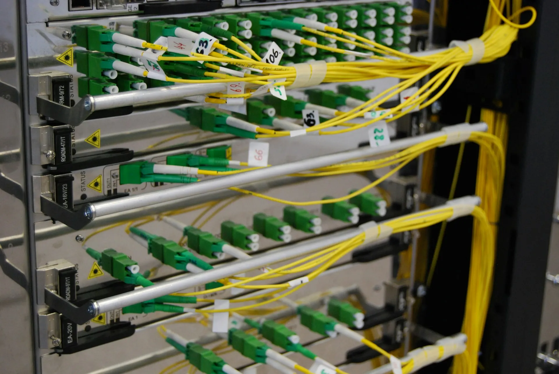
A design like this fits on one drawing, can be maintained by a small team, and leaves room to grow. It is deliberately simpler than an enterprise reference architecture. Every element in it is there because a plant of this size needs it.
How OT network architecture grows: four stages and the triggers between them
Plant networks grow through four stages:
- Flat, with everything on one subnet.
- Machines isolated behind PLCs or NAT.
- A managed backbone with VLANs and one Layer 3 core.
- A defined enterprise boundary with a DMZ and monitoring.
Each move has a trigger: a second line, a connection to IT, a remote-access request, an outage or an audit. Most plants sit at different stages in different areas.
| Stage | What it looks like | Trigger to move on | First three actions |
|---|---|---|---|
| 1. Flat | One subnet, unmanaged and managed switches mixed, devices added as needed | A second line, an outage nobody can explain, or a request to connect to IT | Draw the as-built network; inventory devices and addresses; find the bypasses to IT and the internet |
| 2. Machines isolated | PLCs and NAT devices keep machine traffic private; the plant side is still flat | Growing device count, more than one team making changes, a plan to connect MES or a historian | Choose the core switch; define the VLAN plan; set up a management VLAN |
| 3. Managed backbone | Area VLANs routed at one Layer 3 core, access lists between areas | Enterprise systems need plant data, remote access requests, an insurer or customer audit | Install the boundary firewall and DMZ; move remote access into the DMZ; turn on passive monitoring |
| 4. Defined boundary | Firewall and DMZ between plant and office, monitored network, documented ownership | Multi-site standardisation or regulatory scope | Zones and conduits under IEC 62443; formal change control; periodic review |
This is where the “black or white” framing fails. A 60-device plant with one line and no connection to IT does not need stage 4 tomorrow. It needs a drawing, an inventory and a plan. A 400-device plant still at stage 1 is running on luck. In most plants we walk into, the answer is mixed: the newest line arrived from the OEM at stage 2, the utilities are at stage 1, and someone has started a VLAN plan that was never finished. The design job is to decide which area moves next and why. If you want an outside view of that, we run an assessment of where your plant network stands today.
Mistakes IT teams make on their first plant network
The common mistakes come from applying good IT habits without OT context: scanning live controllers, changing switch settings during production, running DHCP on control networks, locking engineering laptops to one subnet, pulling every unmanaged switch, and owning the network without the controls team.
- Active scans on live controllers. A vulnerability scan that is routine on the office network can fault an older PLC or network module. Scan during shutdowns, with the controls team present, or use passive tools.
- Switch changes during production. Changing spanning tree priorities, trunk settings or firmware on a switch that carries I/O can drop connections across a line. Schedule changes in maintenance windows, with a rollback plan.
- DHCP on control networks. Addresses that change break connections hard-coded in PLC and HMI programs. Use static addresses from a plan.
- Engineering laptops locked to one subnet. A laptop that cannot reach the machine it is meant to program forces technicians onto personal or vendor laptops, which is worse. Build a sanctioned engineering path instead.
- Removing every unmanaged switch. The switch inside an isolated machine is rarely the risk. The one bridging areas or reaching IT is.
- Patching without a window. OT patches are tested and installed during planned downtime, often on the vendor’s compatibility list, not on Patch Tuesday.
- Owning the network without the controls team. The people who know which device does what are in maintenance and engineering. Design without them and the first change will break something nobody predicted.
- No as-built drawing. If the current network is not drawn, every other improvement starts with a guess.
Ownership works best when it is shared and explicit. IT typically owns the boundary firewall, the DMZ, the core switching standard and the management VLAN. Engineering or maintenance owns the machine networks and anything that can stop a line. Each boundary has a named owner, and every change that touches production goes through one change process both sides respect.
Frequently asked questions
Do I need managed switches on a plant network?
On the backbone and anywhere traffic crosses between areas, yes. Managed switches give you VLANs, IGMP snooping, port diagnostics and ring redundancy. Inside a small machine network isolated behind a PLC, with a handful of devices and slow update rates, an unmanaged switch is acceptable. Rockwell and ODVA both publish those conditions. The mistake is letting unmanaged switches carry traffic between areas or toward IT.
Should PLCs be on the same network as office computers?
No. Put a firewall between the plant network and the office network, and allow only the traffic each side needs, ideally through a small DMZ. NIST SP 800-82 recommends firewall rules that only permit connections between adjacent levels, so business systems never reach controllers directly. A PLC on the office network is exposed to every laptop, scan and infection on that network.
How many VLANs does a small manufacturing plant need?
For a single site of about 200 devices, one to five VLANs is usually enough: one for supervisory systems, one per production area or line, and one for network management. Segment by area and function rather than by device type. Splitting PLCs and HMIs into separate VLANs forces every HMI poll through the router and adds load without adding much protection.
How do I connect a machine that ships with 192.168.1.x addresses?
You have two good options. Keep the machine’s devices private behind its PLC and give only the PLC a plant address, or put a NAT device in front of the machine and translate only the addresses the plant needs to reach. Use one NAT device per machine when several machines share the same addressing. Set the default gateway on every private device and document the translation table.
Is the Purdue model still relevant for OT network architecture?
Yes, as a map of trust rather than a wiring diagram. The Purdue model sorts systems into levels and says traffic should move only between adjacent levels. That is still the clearest way for IT and engineering to agree who may talk to whom. Where it goes wrong is treating every level as a separate physical network in a small plant, or dismissing it because edge and cloud exist.
Who should own the OT network, IT or engineering?
Both, with a named owner for each boundary. IT usually owns the firewall, the DMZ and the core switching standards. Engineering or maintenance owns the machine networks and anything that can stop a line. Changes that touch production go through a shared change process with a maintenance window. Plants get into trouble when one side owns the network alone and the other side works around it.
Where does your plant network stand today?
Most plants we walk into are at stage 1 or 2. The network works, mostly, and nobody has a current drawing of it. That is a reasonable place to start from, not a failure. The useful question is which stage each area of the plant is in, and which trigger is coming next: a new line, a request to connect the MES, an insurer’s questionnaire, or the outage nobody wants to repeat.
Ten questions, about two minutes
Where does your plant network stand?
Answer honestly. Each answer opens the next question, and the end shows your gaps.
- Do you have a drawing of the plant network that matches what is installed today? Every other improvement starts from it. Without one, every change is a guess.
- Can a computer on the office network reach a PLC, HMI or drive directly? Business systems should never reach Level 2 or below. NIST SP 800-82 limits traffic to adjacent levels.
- Is there a firewall between the plant network and the office network? One enforced boundary, with a DMZ for shared services, is the minimum for any plant connected to IT.
- Do you know every remote-access path into the plant, including boxes installed by machine builders? OEM remote-access devices with their own internet connection bypass every boundary you build.
- Is the plant divided into VLANs by area, routed at one Layer 3 point? One broadcast domain lets a single looped cable or chatty device reach every controller on site.
- Are drives, remote I/O and vision devices kept on private networks behind their PLCs where possible? Machine traffic that stays at the machine cannot load the backbone or be reached from it by accident.
- Do machines that arrive with identical addresses, such as 192.168.1.x, sit behind NAT or their PLC? Two identical machines on one subnet is a duplicate-address outage waiting for the second one to power up.
- Are the switches that carry traffic between areas managed, with IGMP snooping and a querier? Unmanaged switches flood multicast to every port and give you no diagnostics when something goes wrong.
- Are control devices on static addresses from a documented plan? PLC and HMI programs reference addresses directly. A device that changes address breaks connections nobody remembers.
- Does each network boundary have a named owner, with one change process that IT and engineering both follow? A change one team makes without telling the other is how a network that worked yesterday stops working today.
A good OT network architecture for a small or medium plant is not the most sophisticated one. It is the simplest design that keeps machine traffic local, puts one enforced boundary between the plant and the office, and can be drawn, explained and maintained by the people who run the site.
If you want an outside view, we run an OT network assessment that maps what is actually connected, finds the flat spots and the bypasses, and gives you a staged design your team can build and maintain. Send us a message and we’ll start with a conversation about your plant.
References and further reading
- Ethernet Reference Manual (ENET-RM002) · Rockwell AutomationTopologies, resiliency classes, when unmanaged switches are acceptable, VLAN and NAT guidance.
- Converged Plantwide Ethernet (CPwE) Design and Implementation Guide (ENET-TD001) · Cisco Systems and Rockwell AutomationThe reference architecture most plant network designs descend from.
- Securely Traversing IACS Data across the Industrial Demilitarized Zone (ENET-TD009) · Cisco Systems and Rockwell Automation
- OEM Networking within a Converged Plantwide Ethernet Architecture (ENET-TD018) · Cisco Systems and Rockwell AutomationMachine builders, NAT and how machines join a plant network.
- Network Infrastructure for EtherNet/IP: Introduction and Considerations (PUB00035R0) · ODVA
- PROFINET Design Guideline (Order No. 8.062, Version 1.59) · PROFIBUS & PROFINET International
- SP 800-82 Rev. 3: Guide to Operational Technology (OT) Security · National Institute of Standards and TechnologySection 5.2.3.1 covers network architecture and segmentation.
- IEC 62439-3:2021 Parallel Redundancy Protocol (PRP) and High-availability Seamless Redundancy (HSR) · International Electrotechnical Commission