
PLC Programming
OTU Instruction (Output Unlatch): Designing the Reset in a PLC
The OTU instruction clears a latched bit. Why Reset fails while a fault is active, set vs reset dominance, first-scan clears, and 15 vendor editors.

Table of contents
Most pages describe the OTU instruction in one line: it turns off what OTL turned on. That is true and it is not the useful part. Output Unlatch is where you decide how a latch ends: what clears it, when it is allowed to clear, and which side wins when the set and the reset are both asking at once. Get those three decisions right and your faults, alarms and batch flags behave predictably. Leave them to chance and you get the classic complaints: “Reset does nothing”, “the alarm cleared itself”, “the sequence skipped a step”.
This page is the partner of the OTL page, which covers latching, retention and power-up. Here the focus is clearing and reset design. As with the other instruction pages in this guide, there is a quiz and five harder problems at the end, and every animation has a pause control.
The short version. OTU writes 0 to its bit while its rung is true and does nothing when the rung is false. It cannot hold a bit off against an OTL whose rung is still true; within one routine, the later rung in the scan decides the bit at the end of the scan. Design every reset to answer three questions: what clears it, when it may clear, and which side wins.
What is the OTU instruction?
The OTU instruction, short for Output Unlatch, is a ladder logic output instruction that clears one bit. When its rung is true, OTU writes 0 to the bit. When its rung is false, it leaves the bit alone. It is normally paired with an OTL on the same bit. Other vendors call it a reset coil or an RST instruction.

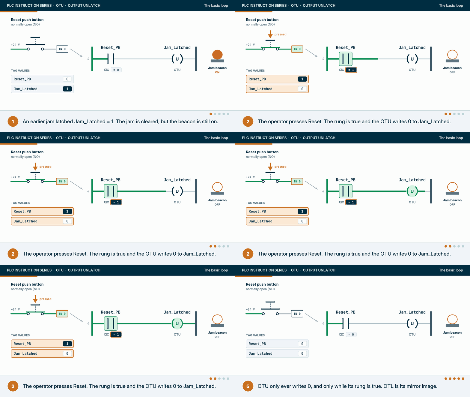
Rockwell’s Logix 5000 general instructions reference manual (publication 1756-RM003) gives OTU one BOOL operand, the bit to be cleared, and this execution table:
| Condition when the OTU executes | What happens to the bit | Rung condition out |
|---|---|---|
| Prescan (when the controller enters Run mode) | Not modified | False |
| Rung condition coming in is false | Not modified | False |
| Rung condition coming in is true | Cleared to 0 | True |
| Postscan | Not modified | False |
Source: Rockwell Automation, Logix 5000 Controllers General Instructions Reference Manual, 1756-RM003, revision P, OTU section.

It is the mirror of the OTL table: one row writes, three rows leave the bit alone. The manual adds that OTU does not affect the arithmetic status flags, has no fault conditions, and exists in relay ladder only. In structured text the equivalent is IF Reset_PB THEN Jam_Latched := 0; END_IF;. Rockwell’s SLC 500 manual (1747-RM001) describes the pair the same way: OTL can only turn a bit on, OTU can only turn it off, and they are usually used together on the same bit.
Why does Reset not work while the fault is still there?
Because the OTL sets the bit again. While the condition that latched the fault is still true, the OTL writes 1 on every scan. The OTU clears the bit for the rungs below it, then the OTL sets it again on the next scan. The bit is 1 only between the two rungs, so the fault appears cleared while Reset is held and comes straight back when it is released.

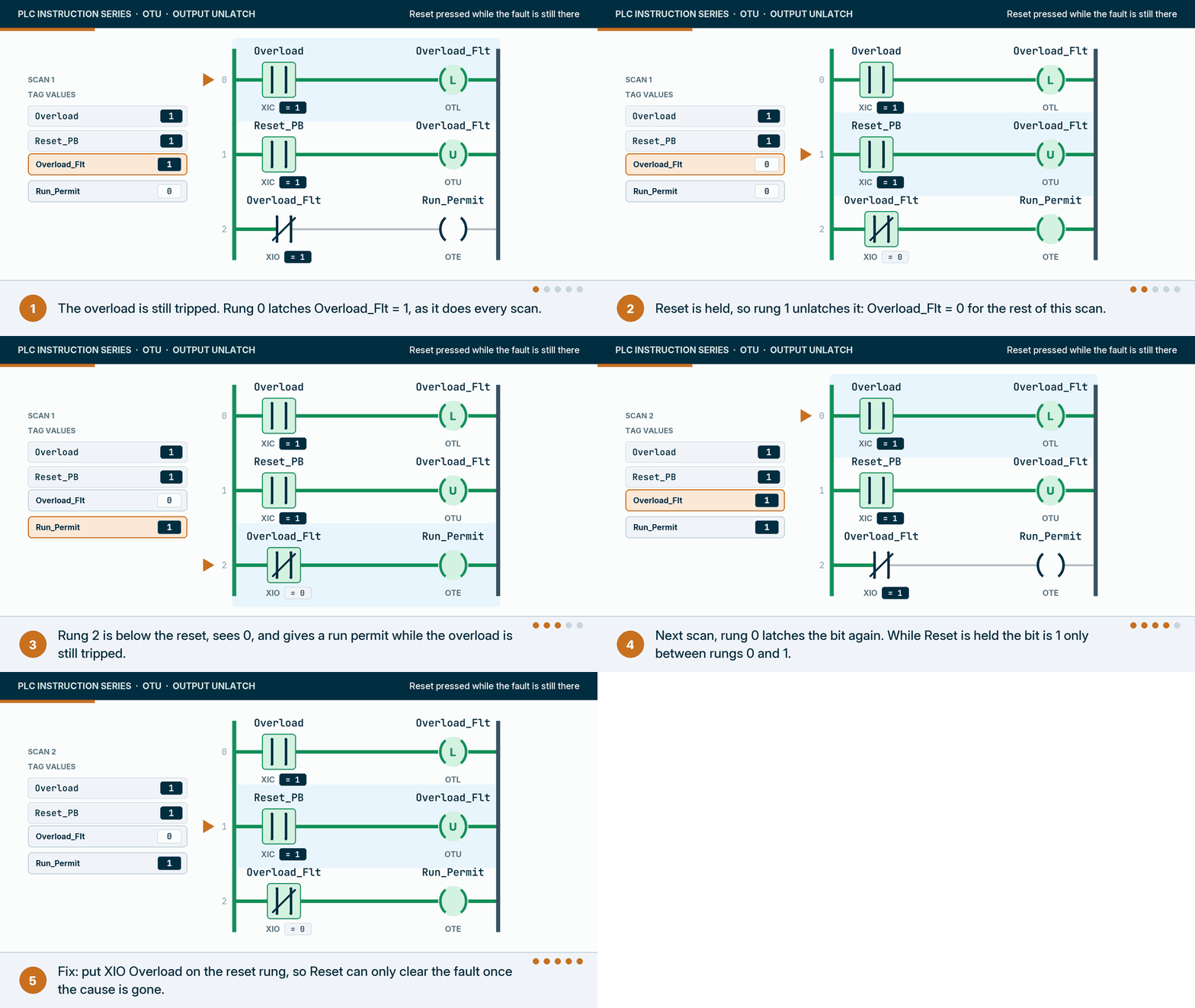
The animation shows a worse problem than a fault that comes back. With the reset rung above the run permit, Run_Permit is 1 at the end of every scan while Reset is held, so a motor wired to it gets its permit while the overload is still tripped.
The fix is to make the reset conditional on the cause being gone:
| Reset rung | While the fault is still present | After the cause has gone |
|---|---|---|
XIC(Reset_PB) OTU(Overload_Flt) | Clears the bit for the rest of each scan; the fault appears cleared while Reset is held, rungs below it see 0, and it returns on release | Clears the fault |
XIC(Reset_PB) XIO(Overload) OTU(Overload_Flt) | Does nothing; the fault stays latched and every rung sees 1 | Clears the fault |
The second version is what I would put in any program. Pair it with an HMI indication of “fault still active” so the operator knows why Reset was refused.
Which wins when OTL and OTU are both true?
The one that executes later in the scan. Both instructions write the same bit when their rungs are true, so the second write is the one the bit keeps at the end of the scan. Put the OTU below the OTL and reset wins; put the OTL below the OTU and set wins. Rockwell does not state this as a rule in the manual pages we read; it follows directly from the execution tables and scan order.

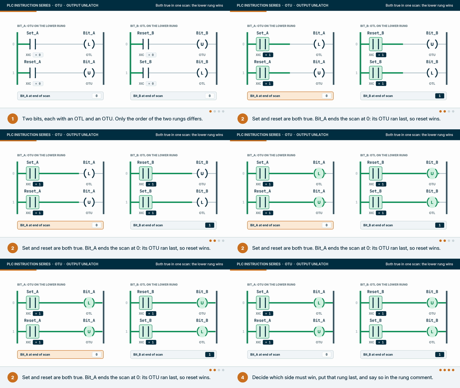
Which side should win depends on what the bit means:
- Reset-dominant (OTU last) suits a run or enable bit: if stop and start are both asserted, stopping must win.
- Set-dominant (OTL last) suits a fault or alarm bit: if the fault is still present when someone presses Reset, the fault must stay. In practice the cleaner way to get this is the conditional reset above, which makes the dominance explicit instead of depending on rung order.
Whatever you choose, write it in the rung comment. Rung order is invisible, and the next person to “tidy up” the routine can reverse the behaviour without changing a single instruction.
SR and RS blocks: check the vendor’s definition
Many platforms also offer a bistable function block that does the same job as an OTL/OTU pair in one box, called SR or RS. In CODESYS, Beckhoff TwinCAT and Phoenix Contact PLCnext Engineer, SR is set-dominant and RS is reset-dominant, which is how the IEC 61131-3 names are generally read; all three document it. Siemens’ S7-300/S7-400 ladder manual describes its SR flip-flop as reset-dominant and its RS flip-flop as set-dominant, the opposite way round. Do not assume dominance from the block’s name; read the help for the platform you are on, and test it in a simulator.
OTU vs OTE: two ways to write a 0
OTU writes 0 only when its rung is true. An OTE writes 0 whenever its rung is false. Both put a 0 in the bit, but they mean opposite things: OTU is an event (“clear this now”), OTE is a state (“this bit equals this rung”). Mixing them on one bit is a common source of bugs.
| OTU (Output Unlatch) | OTE on a false rung | |
|---|---|---|
| Writes 0 when | Its rung is true | Its rung is false |
| Writes 1 | Never | When its rung is true |
| During prescan | Leaves the bit alone | Clears the bit |
| Partner | OTL on the same bit | None; it owns the bit alone |
| Mixed on one bit with an OTL | Normal: that is the latch pair | A bug: the OTE writes 0 whenever its rung is false and erases the latch |
How does an OTU behave over time?
The bit only changes while one of the two rungs is true. A set pulse leaves it at 1 after the pulse ends; a reset pulse leaves it at 0. When both are true in the same scan, the later rung decides. Between pulses, the bit simply holds.

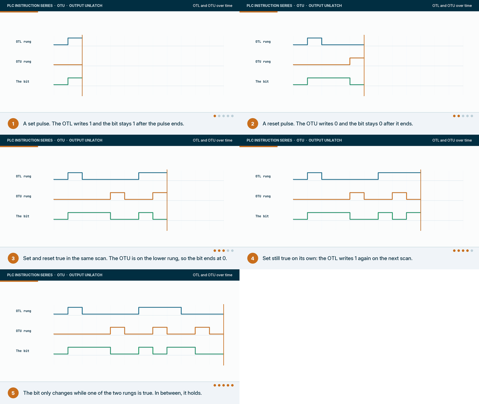
The interesting moment is scan 8 in the chart: set and reset are both true, the OTU is on the lower rung, so the bit ends the scan at 0. On scan 9 the set rung is still true on its own, and the OTL writes 1 again. An OTU is a momentary clear, not a hold-off. If you need “hold this bit off while X”, that is a condition on the OTL rung, not an OTU.
When does an OTU run? Prescan and the first scan
Like OTL, OTU does nothing during prescan, so latched bits come through a mode change unchanged. The usual way to decide what survives a restart is an OTU on the first scan: Rockwell controllers provide a first-scan bit that is 1 on the first scan and 0 after that.

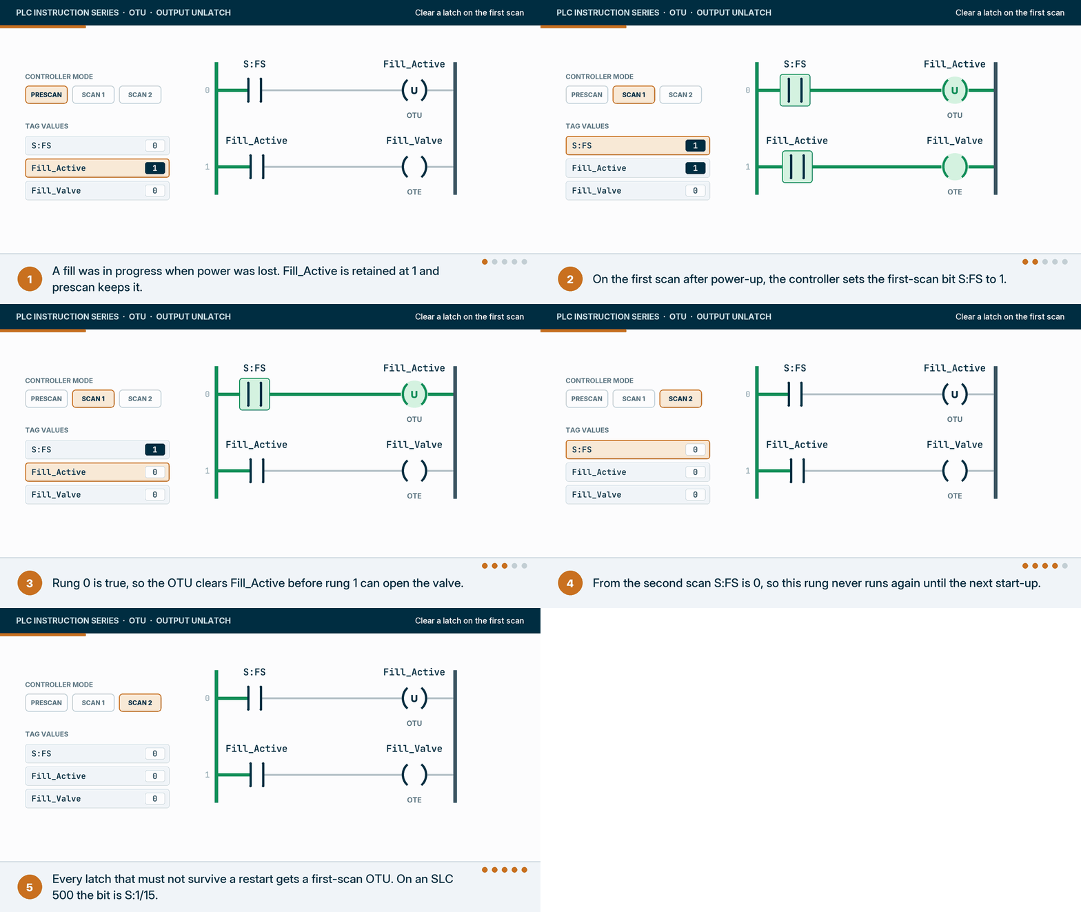
The first-scan bit is S:FS in Logix and S:1/15, the first pass bit, on an SLC 500. Rockwell’s SLC 500 manual shows the same technique for the retentive outputs of specialty I/O modules: it unlatches them with the first pass bit to prevent unexpected start-up at power-up. Test on your Logix controller whether S:FS also fires when you switch from Program to Run, not only at power-up. Two details matter:
- Put the first-scan rung where it runs first. The first-scan bit is only 1 for one scan, so the OTU must be in a routine that is scanned on that scan, above any rung that acts on the bits it clears.
- Clear only what should not survive. Some latches should survive a restart: a tripped high-high level, a quality hold. Decide bit by bit, and comment the decision.
Designing a reset: three questions
Every reset rung answers three questions, whether or not anyone asked them. Asking them on purpose is most of what makes a latch safe to live with.
- What clears it? An operator’s reset button, an HMI acknowledgement, the start of the next batch, the next step of a sequence, the first scan, or a part leaving the station.
- When may it clear? Only once the cause has gone; only while the machine is stopped; only from a particular location; only for an authorised user. Each “only” is a condition on the OTU rung.
- Which side wins? If the set and reset conditions can be true together, decide which should prevail and put that rung last, or make the conditions mutually exclusive.
OTU in practice: seven scenarios from simple to advanced
Each scenario shows a rung in a particular state, why OTU is the right instruction, and what goes wrong. Tag names are examples, written the way I would want them in a real program.
1. Specialty chemicals: clear last batch’s step flags
A batch sequence latches a done flag as each step completes. When a new batch starts, last batch’s flags must be cleared before any step can read them.

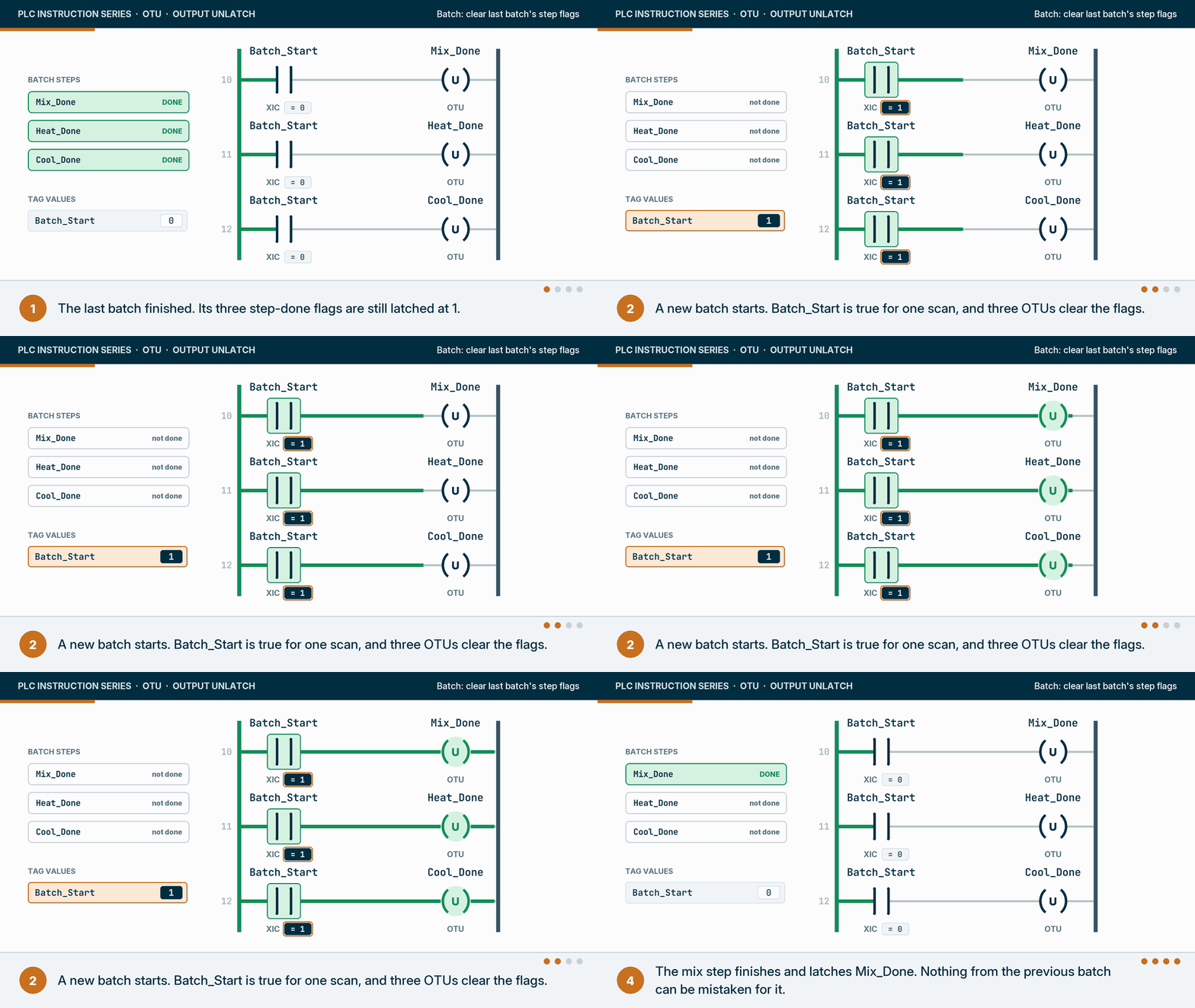
Why OTU: the flags are memory, and the batch start is the event that makes them stale. What goes wrong: the batch-start rung below the sequence rungs. For one scan, the sequence reads last batch’s flags and can advance a step before they are cleared. Put the clear above everything that reads the flags, and drive it from a one-shot so it runs exactly once per batch.
2. Packaging: acknowledge silences, reset clears
On a case sealer, a low seal temperature latches a fault and sounds a horn. Operators need to silence the horn straight away, but the fault itself must only clear once the sealer is back at temperature.
Why OTU: acknowledging and resetting are two different events with two different conditions, and each is a clear of a different latched bit. What goes wrong: using one button for both. Then either the horn cannot be silenced until the fault is gone, which trains people to ignore horns, or the fault clears while the sealer is still cold. Alarm-management practice, including the ISA-18.2 standard, separates acknowledging an alarm from the alarm returning to normal.
3. Water and wastewater: reset a pump fault only while it is stopped
The booster station from the OTL page latches pump 2’s fail-to-start. The reset must not make the pump available while the station is calling it, or the pump would start the instant the reset is pressed.
Why OTU: the failure is a latched state, and clearing it is a deliberate act with conditions. What goes wrong: a remote reset from SCADA. An operator miles away clears the fault, the station calls the pump, and nobody has looked at it. Some utilities restrict certain resets to the local panel, which is a condition on the OTU rung (a local/remote selector bit), not a policy document.
4. Brewing: reset a high-high trip only when it is safe
A fermenter’s high-high level switch latches a trip that closes the fill valve. The trip must not clear while the level is still at the switch.

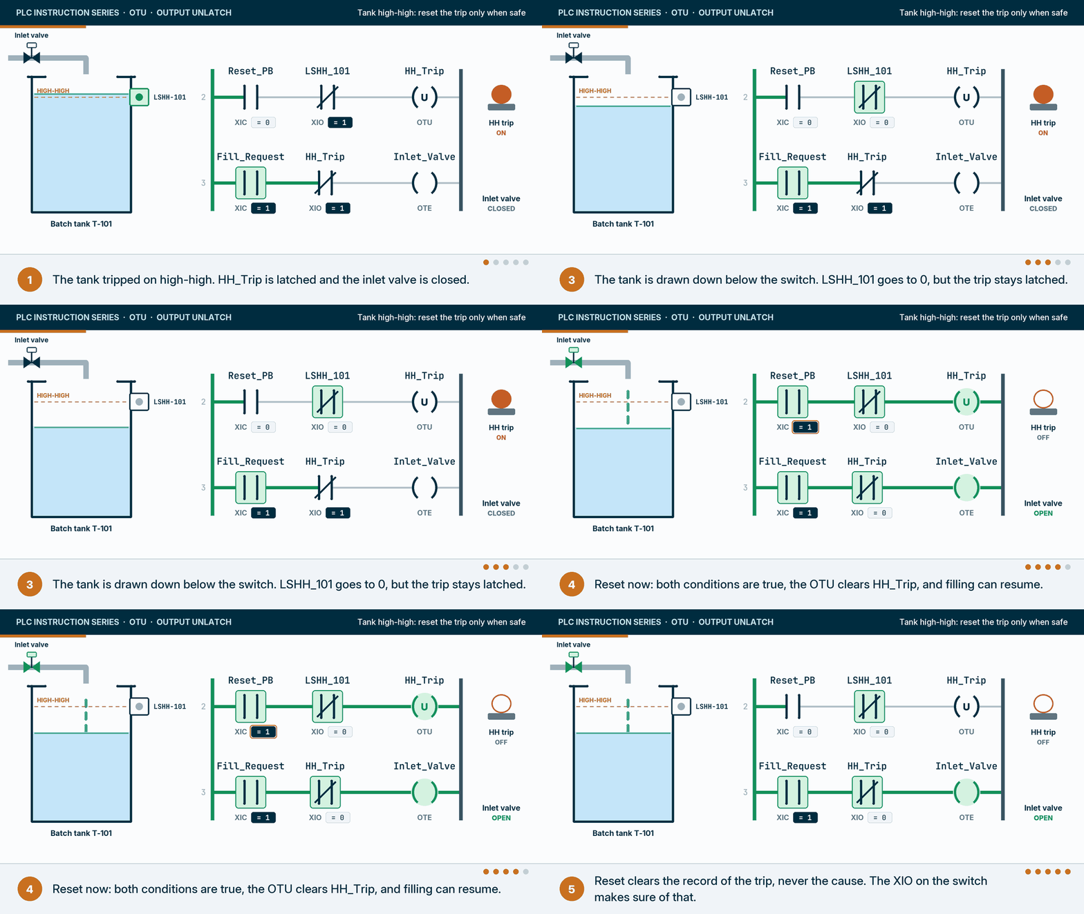
Why OTU: clearing the trip is a decision a person makes after looking, with the process already back in a safe state. What goes wrong: treating “the switch is clear” as “it is safe to fill”. The trip happened for a reason, a stuck valve or a wrong transfer, and the reset should be the moment someone confirms it was found. For trips that protect people or the environment, the reset belongs to the independent protective layer, which usually needs its own manual reset by design.
5. Food and beverage: a pasteuriser lockout that clears only after a clean
A pasteuriser diverts flow when the holding tube temperature falls below its legal minimum, and some plants lock out forward flow until the line has been sanitised.
Why OTU: the lockout must survive until a specific sequence of events is complete, and only then may it clear. What goes wrong: the regulatory layer. In many jurisdictions pasteuriser divert logic is a regulated public-health control with sealed settings and its own approved controls. A standard PLC rung like this one should not be the only control unless your regulator has approved it as the divert control. In many jurisdictions the divert logic, its settings and who may reset it are covered by specific rules; check them before you write it.
6. Pharmaceutical: a recipe change clears the line clearance
After a product changeover, a line clearance confirms that no material from the last product is left. Loading a new recipe must invalidate any earlier clearance.
Why OTU: the clearance is a latched permission, and a different recipe in use is the condition that makes it invalid. What goes wrong: missing a path. Recipes can be changed from the HMI, from a manufacturing execution system, or by a download. Every path must trigger the clear, so it is safer to clear on “recipe in use is not the recipe that was cleared” than on each individual way of changing it.
7. Automotive: clear the reject flag when the part has gone
The torque reject latched on the OTL page must be cleared once the rejected part has left the station, so the next part starts clean.
Why OTU: the flag belongs to one part, and the part leaving is the event that ends its life. What goes wrong: clearing on the reject gate firing alone. If the push-off fails, the flag clears while the bad part is still in the station, and it travels on as good. Clear on proof that the part has gone, not on the command that was meant to remove it.
What does OTU look like in each vendor’s software?
Every ladder editor has a way to clear a bit. Rockwell Automation calls it OTU in Studio 5000 Logix Designer and RSLogix 500, drawn as a coil with a U (more on those platforms on our Rockwell Automation page). Siemens calls it a reset output, and CODESYS, Phoenix Contact and AutomationDirect call it a reset coil, drawn with an R or the word RST. Mitsubishi Electric uses the RST instruction and Omron uses RSET.
| Vendor | Software | Name of the instruction | Example operand | Text form |
|---|---|---|---|---|
| Rockwell Automation | Studio 5000 Logix Designer | OTU, Output Unlatch | Jam_Latched | Rung text OTU(Jam_Latched); ST IF c THEN Jam_Latched := 0; END_IF; |
| Rockwell Automation | RSLogix 500 (SLC 500, MicroLogix) | OTU, Output Unlatch | B3:0/4, O:2/0 | OTU B3:0/4 |
| Siemens | TIA Portal (S7-1500) | Reset output | "Jam_Latched", %M10.0 | STL R "Jam_Latched" |
| Mitsubishi Electric | GX Works3 (MELSEC iQ-R) | RST instruction | M10, Y20 | RST M10 |
| IEC 61131-3 / CODESYS, Beckhoff | CODESYS, TwinCAT 3 | Reset coil | A named BOOL variable | ST IF c THEN bJam := FALSE; END_IF; |
| Phoenix Contact | PLCnext Engineer | Reset coil | A named BOOL variable | ST conditional assignment |
| AutomationDirect | CLICK Programming Software | Reset coil | C10, Y001 | None; ladder only |
Sources: Rockwell Automation 1756-RM003 and 1747-RM001; Siemens STL for S7-1500 and the S7-300/S7-400 LAD manual; Mitsubishi Electric FA FAQ 22456; CODESYS and Beckhoff online help; Phoenix Contact PLCnext Engineer help; AutomationDirect CLICK help.
The same unlatch in each vendor’s editor
These are real screenshots of the reset coil in 15 programming environments, ordered the same way as on the other instruction pages. Each one is framed the same way, with the instruction ringed in amber and the source credited under it. Pick a tab to switch software.
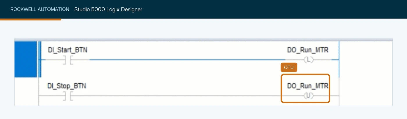
DO_Run_MTR, driven by an XIC on DI_Stop_BTN. It clears the bit that the OTL on rung 0 latched. Screenshot: RealPars, PLC Latching vs Sealing Explained Simply.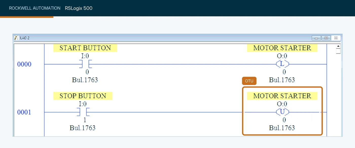
O:0/0 (MOTOR STARTER), driven by an XIC on I:0/1 (STOP BUTTON). It clears the bit the OTL on rung 0000 latched. Screenshot: SolisPLC, PLC Programming Fundamentals: OTU Output Unlatch Instruction.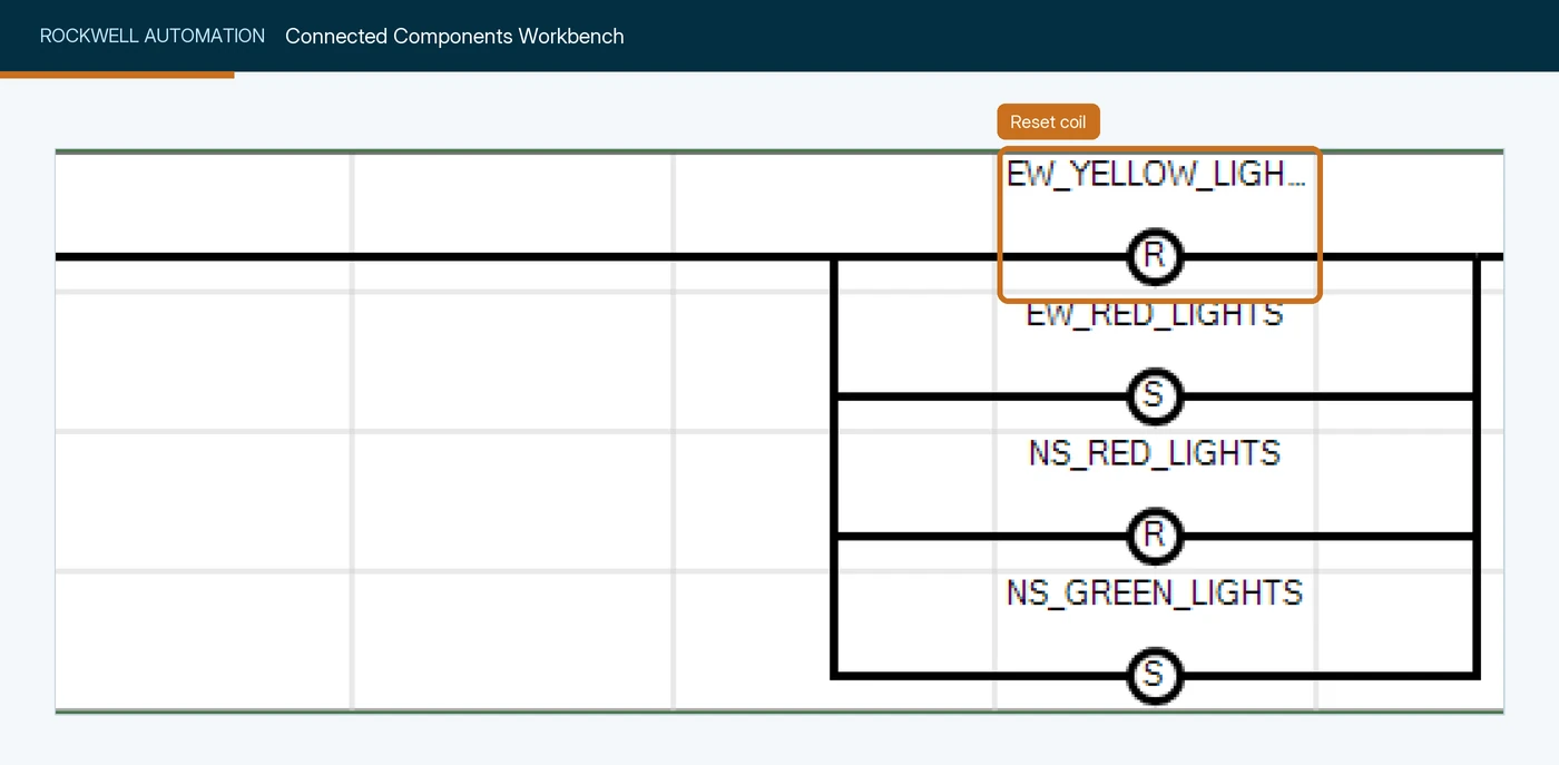
EW_YELLOW_LIGHTS, switching that light off once TON_2 has timed out, in parallel with set coils for the next lights. Screenshot: Rockwell Automation, Micro800 and Connected Components Workbench Getting Started Guide.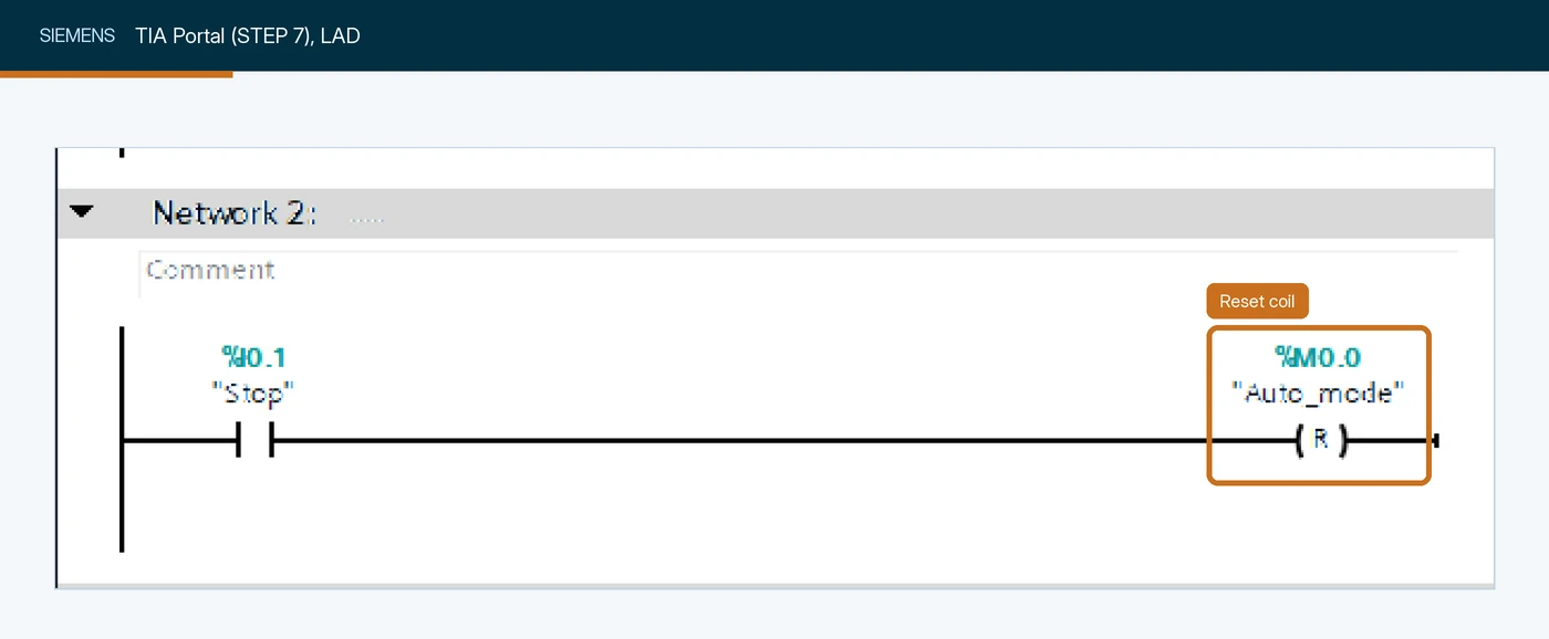
"Auto_mode" (%M0.0), driven by a normally open contact on "Stop" (%I0.1). It writes 0 to the tag, undoing the Set coil from Network 1. Screenshot: SolisPLC, An Introduction to Basic Ladder Logic Instructions in Siemens TIA Portal.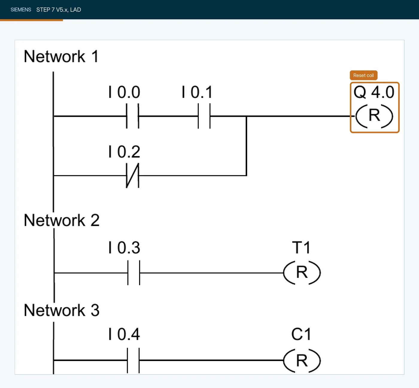
-(R)- on Q 4.0, switched off when I 0.0 and I 0.1 are true or I 0.2 is false. Siemens calls it "Reset output". Screenshot: Siemens AG, Ladder Logic (LAD) for S7-300 and S7-400 Programming.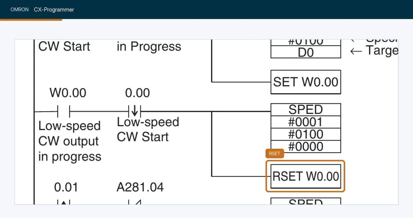
RSET W0.00 instruction, which turns W0.00 off and keeps it off, undoing the SET W0.00 on the rung above. RSET is Omron's reset. Screenshot: Omron, CP1E CPU Unit Software User's Manual (W480).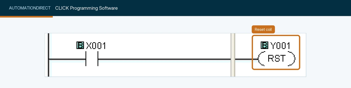
Y001, which turns the bit off when the contact on X001 goes true. Screenshot: AutomationDirect, CLICK help, Reset Coil.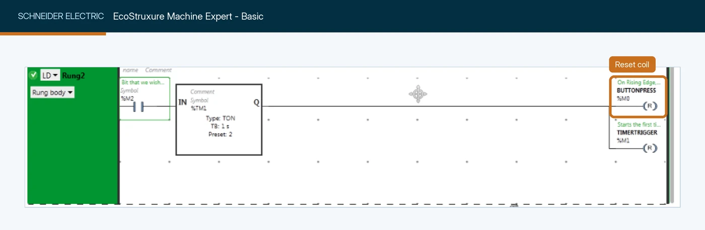
R) on memory bit %M0 (BUTTONPRESS) in rung 2, enabled by a timer output. Screenshot: Schneider Electric, FAQ FA383792 (Machine Expert - Basic project).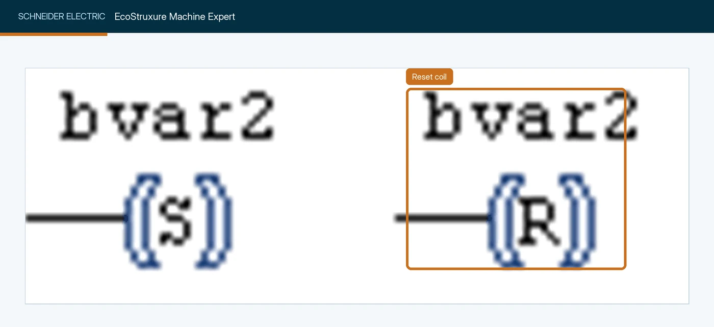
R) on variable bvar2, shown beside its set counterpart. Screenshot: Schneider Electric, Machine Expert help, Set/Reset Coil.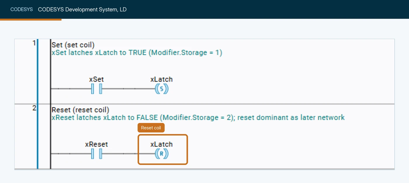
R) on xLatch, enabled by the xReset contact. Screenshot: CODESYS Group, CODESYS 4 online help, Binary circuits.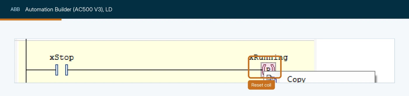
xRunning, energised by the xStop contact. Screenshot: ABB, AC500 V3 PLC - Bistable, Counter, Timer & Trigger (Technical Note 12).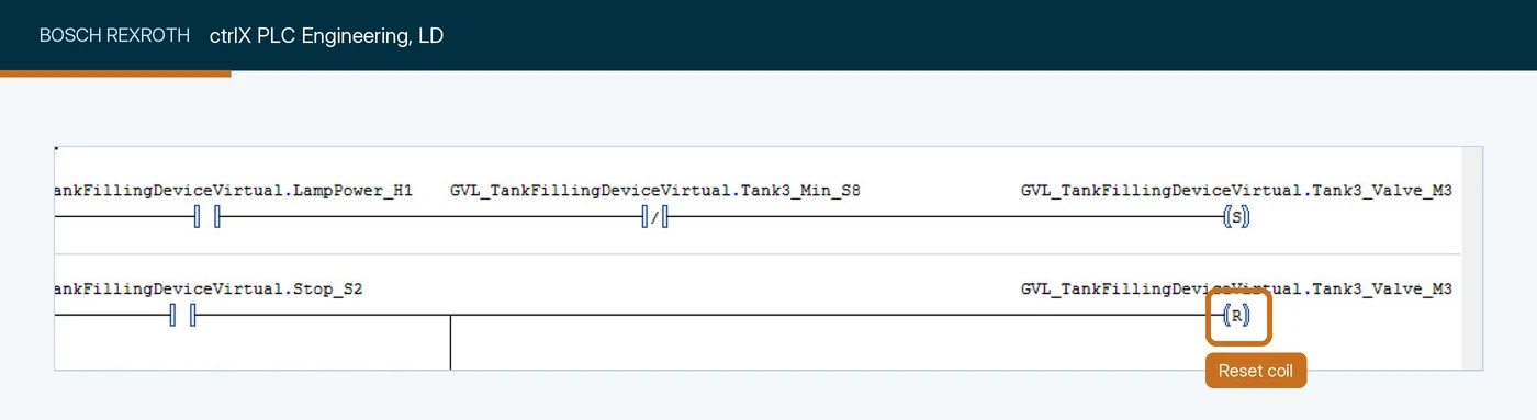
Tank3_Valve_M3, energised by the Stop_S2 contact. Screenshot: Bosch Rexroth community, How to run a ladder diagram simulation using ctrlX PLC 1.20.7 (forum post).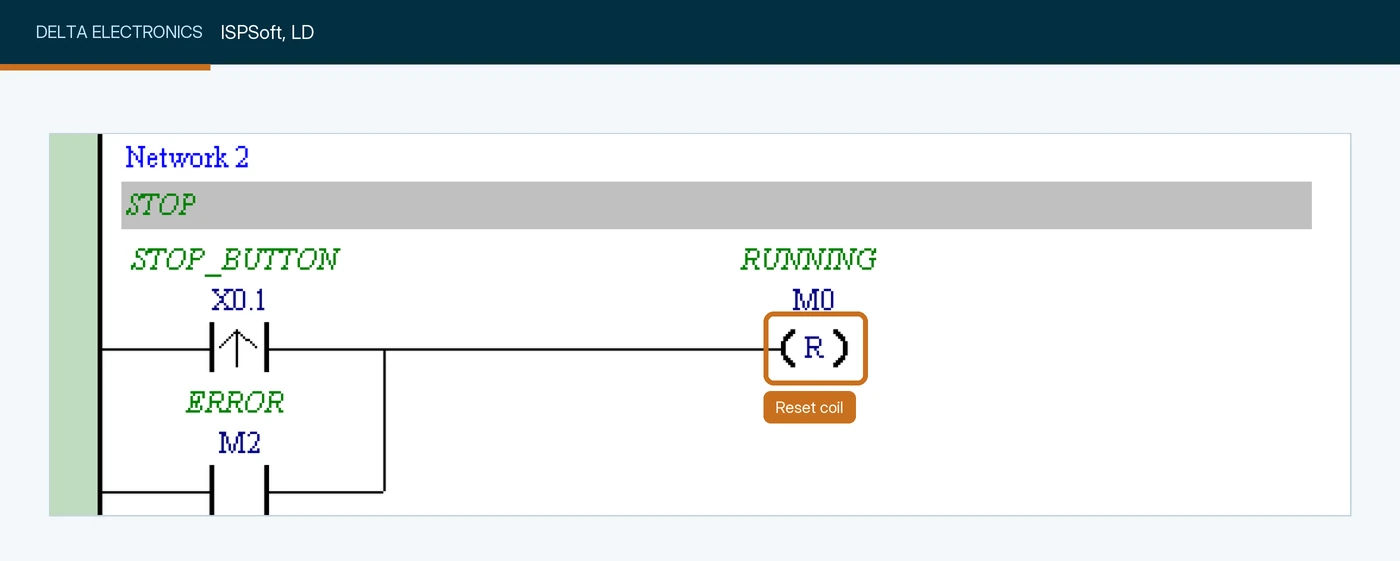
M0, energised by a rising-edge stop contact on X0.1 or the error contact M2. Screenshot: Delta Electronics, ISPSoft User Manual.
Y0, triggered by a rising-edge contact on X1. Screenshot: Panasonic Industry, Control FPWIN Pro7 help: SET / RST.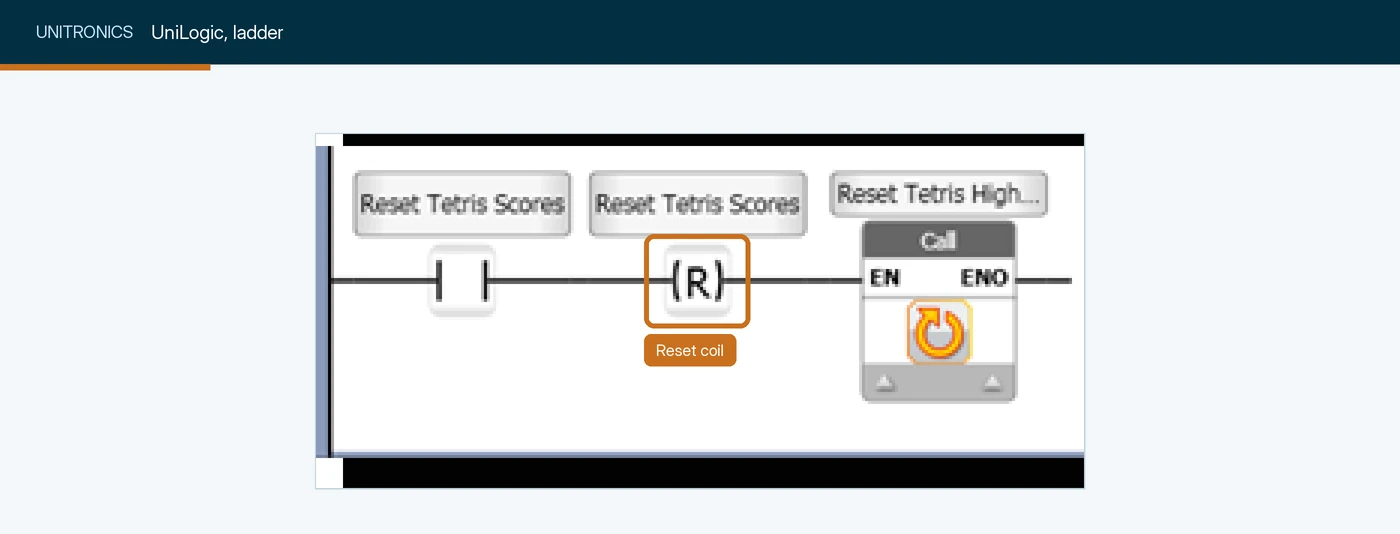
Call block. Screenshot: Unitronics, UniLogic Help: Show Code.| Vendor | Software | Why it is not shown yet |
|---|---|---|
| Siemens | LOGO!Soft Comfort | We found no reset coil in LOGO! ladder in the V8.4 help; latching and unlatching are done with the RS latching relay block. |
| Omron | Sysmac Studio | No public screenshot of a RESET coil in the editor; the manual shows drawn symbols only. |
| AutomationDirect | Productivity Suite, Do-more Designer | No public screenshot of a reset coil or RST instruction in these editors. |
| Mitsubishi Electric | GX Works3, GX Works2 | The training manuals show RST as a drawn figure, not an editor window. |
| Schneider Electric | EcoStruxure Control Expert | The manual’s LD chapter shows only drawn symbols. Machine Expert and Machine Expert - Basic are shown above. |
| Beckhoff | TwinCAT 3 | No public screenshot of a reset coil in the TwinCAT 3 LD editor. |
| Emerson | PAC Machine Edition | No public screenshot of a reset coil in the editor. |
| Phoenix Contact | PLCnext Engineer | No public screenshot of a reset coil in the editor. |
| KEYENCE, B&R, Inovance | KV STUDIO, Automation Studio, InoProShop | No public screenshots of the ladder editors (see the XIC page for the search trail). |
If you work in one of these, the instruction is the same reset; we will add your editor when we capture it ourselves.
One platform difference matters for OTU in particular. Mitsubishi Electric’s GX Works3 has a duplicated-coil check, and its own FAQ notes that SET and RST on one device are not flagged, because that pair is meant to share a device. So the editor will not warn you about a latch pair; it is up to the rung comments to say which side wins. If you want a practice environment, I have walked through installing RSLogix 500 for free and TIA Portal.
Why won’t my OTU clear the bit? A debugging checklist
When a reset does not reset, the OTU is almost never broken. Something sets the bit again, or the OTU never runs.
- Watch the OTU rung while Reset is pressed. If the rung is not true, debug its conditions: the button, its input, any “only when” permissives.
- Check the OTL’s rung. If the latch rung is still true, the OTL sets the bit again on the next scan. Find out why the cause is still present.
- Check rung order. If the OTL runs after the OTU in the same scan, set wins whenever both are true.
- Cross-reference the bit. Look for other writers: a second OTL, an OTE (which writes 1 whenever its rung is true), a MOV or COP on the containing word, or an HMI write.
- Check whether the routine is scanned. An OTU in a routine that is not called never runs.
- Check momentary signals. An HMI reset that is too short, or a pulse that falls between scans of a slow task, may never be seen by the OTU rung.
- Check first-scan logic for the opposite problem. If a bit clears itself after a restart, look for an OTU on
S:FSorS:1/15that clears something it should not.
Common OTU mistakes
| Mistake | What happens | Fix |
|---|---|---|
| Reset rung with no “cause gone” condition | The fault looks cleared while Reset is held, rungs below it see 0, and it returns on release | Add the cause, with XIO, to the reset rung |
| Leaving dominance to rung order without a comment | Someone reorders the rungs and the behaviour flips | Choose the dominant side, put it last, comment it |
| One button for acknowledge and reset | The horn cannot be silenced, or the fault clears too early | Separate acknowledge and reset bits |
| Expecting OTU to hold a bit off | The OTL sets it again on the next scan | Put the hold-off condition on the OTL rung |
| No first-scan clear for latches that drive equipment | Equipment restarts after a mode change or power cycle | OTU on S:FS (Logix) or S:1/15 (SLC 500) |
| Clearing on a command instead of proof | The flag clears while the condition is still there | Clear on feedback: the part left, the valve proved, the level fell |
| Assuming SR/RS dominance from the block’s name | Set and reset priority is the opposite of what you expect | Read the platform’s help and test it |
Test yourself: an interview quiz on OTU
Ten questions, the kind I'd ask in an interview for a controls role to see whether someone really understands OTU. Pick an answer and the explanation appears straight away.
0 of 10 answered
What does an OTU do when its rung is false?
Rockwell's execution table says OTU does not modify the bit when its rung is false. It only writes 0 while its rung is true.
An OTL rung is still true and Reset drives an OTU on the same bit on the rung below. What does Reset achieve?
The OTU clears the bit for the rungs after it, but the OTL rewrites 1 the next time it executes with a true rung. That is why resets should wait for the cause to be gone.
OTL and OTU on the same bit, in the same routine, are both true in one scan, and the OTU is on the lower rung. What is the bit at the end of the scan?
The later instruction in the scan decides the end-of-scan value. OTU last makes the latch reset-dominant.
What is the best way to stop a reset from clearing a fault whose cause is still present?
A condition on the reset rung makes the rule explicit: Reset can only clear the fault once the cause has gone.
Which bit would you use on a Logix controller to clear latches at power-up?
S:FS is the Logix first-scan bit. S:1/15 is the SLC 500 first pass bit.
A first-scan OTU is inside a routine called by a conditional JSR. What is the risk?
The first-scan bit is 1 for one scan only. If the routine is not called on that scan, the clear is missed. Put first-scan logic in a routine that is always called first.
What does an OTU do during prescan?
Like OTL, OTU does not modify its bit in prescan or postscan. Only OTE is cleared by prescan.
What is the difference between acknowledging an alarm and resetting a latched fault?
They are separate events with separate conditions. Combining them on one button either keeps the horn sounding or clears faults too early.
In CODESYS, which bistable block is reset-dominant?
In CODESYS, Beckhoff and PLCnext, RS is reset-dominant and SR is set-dominant. Siemens' S7-300/S7-400 manual describes its blocks the other way round, so always check the platform's help.
What does Mitsubishi Electric call the OTU equivalent?
Mitsubishi Electric uses SET and RST. Its FAQ notes that SET and RST on one device are not flagged by the duplicated-coil check, because the pair is meant to share a device.
That's the bit instructions covered. If you'd like the next instruction in this guide in your inbox, the sign-up is below. It's never needed to see an answer.
Five harder OTU problems
These are commissioning-grade problems. Try each on paper before opening the solution. The rungs are written in Logix rung text: XIC(tag) and XIO(tag) are contacts, square brackets with commas are parallel branches, and OTE, OTL and OTU are the output instructions.
Problem 1: start and stop with a latch pair
A pump is run with XIC(Start_PB) OTL(Pump_Run) on rung 4 and XIO(Stop_PB_NC) OTU(Pump_Run) on rung 3, with a normally closed stop button. An operator holding Start while someone presses Stop finds the pump keeps running. Explain, and fix it so stop always wins.
Show the solution
Both rungs are true while Start is held and Stop is pressed. The OTU on rung 3 clears the bit, then the OTL on rung 4 sets it again, so the bit ends every scan at 1: the latch is set-dominant because the OTL is on the lower rung. Stop loses.
Make it reset-dominant by moving the OTU below the OTL, and make Start conditional on Stop so the two cannot fight:
XIC(Start_PB) XIC(Stop_PB_NC) OTL(Pump_Run);
XIO(Stop_PB_NC) OTU(Pump_Run);
Now stop wins whichever rung runs last, and the rung order is a second safeguard rather than the only one. Add a first-scan OTU too, so the pump does not restart after a power cycle. For a pump, a seal-in OTE does all of this with one rung, which is why I prefer it for equipment.
Problem 2: the alarm that resets itself
A high-temperature alarm uses XIC(Temp_High) OTL(Temp_High_Alm) and XIC(HMI_Alarm_Reset) OTU(Temp_High_Alm). HMI_Alarm_Reset is an HMI button. Operators report that alarms disappear without anyone resetting them, especially after 06:00. You find that a SCADA script writes HMI_Alarm_Reset to 1 every morning at 06:00 to “clear old alarms”, and that the HMI button is configured as “set” rather than “momentary”. Explain and fix.
Show the solution
Two problems combine. The SCADA script writes 1 to HMI_Alarm_Reset and nothing writes it back to 0, and the HMI button sets it to 1 and leaves it there. Once HMI_Alarm_Reset is stuck at 1, the OTU clears the alarm on every scan. A new high temperature latches the alarm, and the OTU on the next rung clears it again: the alarm lives for less than a scan and nobody sees it.
Make the reset an event, and make the program own its life:
XIC(HMI_Alarm_Reset) ONS(Alarm_Reset_ONS) XIO(Temp_High) OTU(Temp_High_Alm);
XIC(HMI_Alarm_Reset) OTU(HMI_Alarm_Reset);
The one-shot means a stuck request clears the alarm at most once, the XIO means it can only clear once the temperature is normal, and the second rung clears the request bit after it has been read, so a “set” button or a script cannot leave it at 1. A Reset pressed while the temperature is still high is refused and must be pressed again. Then remove the SCADA script: clearing alarms nobody looked at defeats the purpose of latching them.
Problem 3: a first-scan clear that does nothing
A mixer program has XIC(S:FS) OTU(Mix_Active) as the first rung of the routine Mixer_Seq. After a power cycle, the mixer resumed mid-batch as soon as the operator re-enabled it. Mixer_Seq is called from MainRoutine by XIC(Mixer_Enabled) JSR(Mixer_Seq, 0), and Mixer_Enabled is a latched bit set from the HMI. Explain why the clear did not run, and fix it.
Show the solution
S:FS is 1 only on the first scan. On that scan, Mixer_Enabled had to be true for the JSR to call Mixer_Seq. After the power cycle Mixer_Enabled was 0 on the first scan, so the routine was not called and the OTU never ran. Mix_Active was still latched, and when the operator re-enabled the mixer the sequence picked up mid-batch. A second risk is ordering: if the JSR rung is below other logic that acts on Mix_Active, that logic runs before the clear. Either way, a first-scan clear inside a conditionally called routine is not guaranteed to run.
Put first-scan logic in a routine that is always called first, for example at the top of MainRoutine or in a dedicated initialisation routine called unconditionally:
XIC(S:FS) [OTU(Mix_Active) ,OTU(Mixer_Enabled) ];and decide for each latched bit whether it should survive a restart. Here, neither the batch nor the enable should: the operator must restart the mixer deliberately.
Problem 4: acknowledge and reset on one button
A filler has one HMI button, Fault_Reset, which both silences the horn and clears latched faults: XIC(Fault_Reset) [OTU(Horn) ,OTU(Low_Air_Flt) ,OTU(Jam_Flt) ]. Operators complain that pressing it while a jam is still being cleared silences the horn but the jam fault immediately returns, while the low-air fault sometimes clears while the pressure is still low. Redesign it with acknowledge and reset as separate actions.
Show the solution
Both faults share the same flaw: the reset rung has no “cause gone” condition. While a cause is still present, the OTU clears the bit for the rest of each scan and the OTL sets it again on the next one. So while the button is held, a fault looks cleared and every rung below the reset sees 0; that is the low-air fault “clearing” with the pressure still low. The jam fault looks the same until the button is released, and then it comes straight back.
Separate the two actions and give each reset its own “cause gone” condition:
XIC(HMI_Ack) ONS(Ack_ONS) OTU(Horn);
XIC(HMI_Reset) ONS(Reset_ONS) XIO(Jam_PE_Blocked) OTU(Jam_Flt);
XIC(HMI_Reset) ONS(Reset_ONS2) XIC(Air_Pressure_OK_Delayed) OTU(Low_Air_Flt);
Acknowledge silences the horn at once, as long as the horn itself is set on a one-shot of each new alarm, so an acknowledged horn stays silent while the alarm persists; reset clears each fault only when its cause has gone, and the low-air reset uses a pressure-OK signal held true for a few seconds by a timer, so chatter cannot clear it. The HMI shows which faults are still active, so “reset did nothing” has an answer on the screen.
Problem 5: two parts, one reject flag
A station uses XIC(Torque_Done) XIO(Torque_OK) OTL(Part_Reject) and clears it with XIC(Part_At_Next_Station) OTU(Part_Reject). At high rate, a bad part is occasionally passed as good and the following good part is rejected. Explain and propose a design that cannot mix them up.
Show the solution
One bit is being asked to carry the state of two parts. When the line runs fast, the next part’s torque result arrives before the previous part has reached the next station. If the new part is good, nothing changes the bit and the old reject is still there, so the good part is rejected. If the old part’s arrival clears the bit just after the new bad part set it, the bad part is passed.
State that belongs to a part should travel with the part. Track each position in a bit shift register or an array of part records, write the torque result into the record for the part at the torque station, and let the reject gate read the record for the part in front of it. The OTU then clears one position’s flag as that part leaves, and no two parts ever share a bit. Shift registers (BSL) and FIFOs will get their own pages in this guide.
Keep learning between pages
Sign up for The Plant-Side Brief, Joltek's free weekly email for controls engineers and technicians. Every answer on this page stays open whether you sign up or not.
Where OTU fits in this guide
OTU is the fifth instruction in Joltek’s PLC Programming guide, and with OTL it completes the bit output instructions. With XIC, XIO and OTE, you now have every instruction in the bit family. The next pages cover the one-shot instructions, then timers and counters. The instruction glossary lists them all.
If your team needs this kind of grounding on its own equipment and programs, that is what our hands-on PLC and SCADA training for plant teams is for.
References and further reading
- Logix 5000 Controllers General Instructions Reference Manual (1756-RM003) · Rockwell AutomationOutput Unlatch (OTU): execution table, prescan and postscan leave the bit unchanged. Read in revision P (December 2014).
- SLC 500 Instruction Set Reference Manual (1747-RM001) · Rockwell AutomationOTL and OTU as a retentive pair; first pass bit S:1/15; unlatching retentive outputs at power-up.
- Ladder Logic (LAD) for S7-300 and S7-400 Programming, Reference Manual (A5E02790079-01) · SiemensSet and reset coils; SR and RS flip-flops and their dominance.
- CODESYS Standard library: SR and RS bistable function blocks · CODESYS Group, online help
- Tc2_Standard: RS and SR · Beckhoff, TwinCAT 3 InfoSys
- Coils (LD) · Phoenix Contact, PLCnext Engineer help
- FAQ 22456: duplicated coil check with SET and RST on one device · Mitsubishi Electric