
PLC Programming
XIC Instruction (Examine If Closed): What It Really Tests in a PLC
The XIC instruction asks one question: is this bit 1 right now? How it works, normally closed stops, XIC vs XIO, 26 vendor editors, and a quiz.

Table of contents
Every ladder program you will ever open is full of normally open contacts, which Rockwell Automation software calls XIC instructions, and most of the confusion about them comes from the name. “Examine If Closed” sounds like the controller is looking at a switch. It isn’t. The XIC instruction asks one question, about one bit in memory, at one moment in the scan: is this bit 1 right now? Get that sentence right and normally closed stop buttons, XIC versus XIO, and “why is my rung green but my output off” all stop being mysteries.
I’ve written this as the reference I wish I’d had earlier in my career, when I was programming controllers myself. It starts from zero, with a push button and a light, and works up to scan timing, prescan, status words from other machines, and how the major vendors write the same instruction. At the end there is an interview-style quiz and five harder problems with worked solutions. The animations show each idea moving, and every one of them has a pause control.
The short version. XIC tests one bit: it is true when the bit is 1 and false when the bit is 0. It does not know or care how the field device is wired. Choose XIC or XIO by asking one question: when this rung should pass, is the bit 1 or 0?
What is the XIC instruction?
The XIC instruction, short for Examine If Closed, is a ladder logic input instruction that checks one bit. If the rung reaching it is true and the bit is 1, XIC passes power to the next instruction. If the bit is 0, it blocks power. Rockwell Automation calls it XIC; most other vendors call the same symbol a normally open contact.
Ladder diagrams describe the result as power flow, a habit inherited from relay panels. Rockwell’s own term is rung condition: each instruction receives a true or false rung condition from its left and passes one to its right. This guide uses both, and means the same thing.
Here is the smallest useful program: one push button, one XIC, one output coil (OTE) and one pilot light.

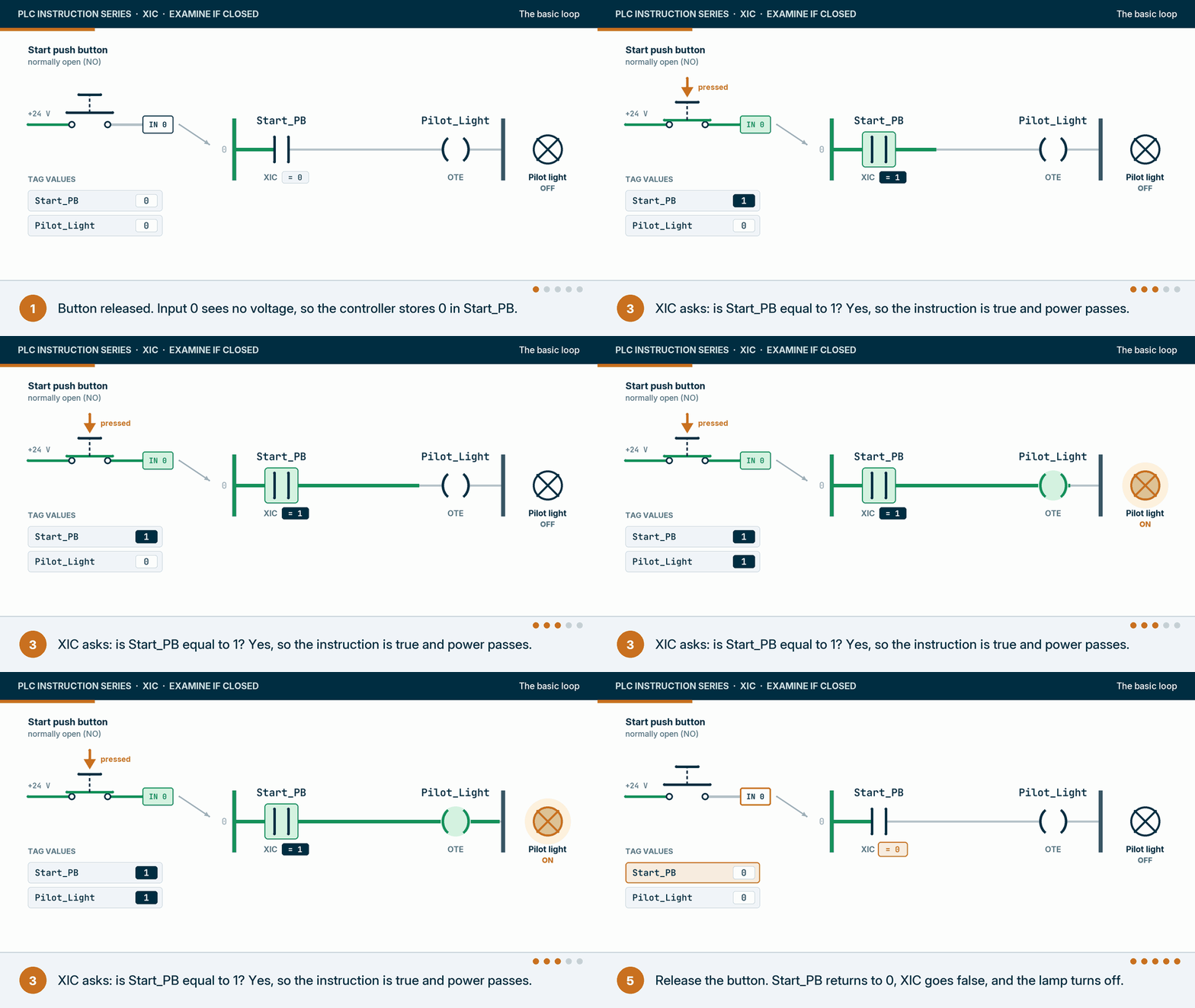
Rockwell’s Logix 5000 general instructions reference manual (publication 1756-RM003) defines XIC with a single operand, a BOOL data bit, and a short execution table. That table is the whole instruction, so it is worth reading once:
| Condition when the XIC executes | Rung condition passed to the right |
|---|---|
| Rung condition coming in is false | False |
| Rung condition coming in is true, bit is 0 | False |
| Rung condition coming in is true, bit is 1 | True |
| Prescan (when the controller enters Run mode) | False |
| Postscan | False |
Source: Rockwell Automation, Logix 5000 Controllers General Instructions Reference Manual, 1756-RM003, XIC section.
The same manual lists XIC as a relay ladder instruction, says it does not touch the arithmetic status flags, and gives it no fault conditions. There is no XIC in Structured Text. You write the bit into an expression instead, for example IF Start_PB THEN.
Why is it called “Examine If Closed”?
The name comes from relay logic, the hard-wired control panels ladder diagrams were invented to replace. In a relay panel a contact really was a piece of metal that was either closed or open, and a rung really did conduct when the contacts in series were closed. Early PLCs kept the drawings so electricians could read them, and kept the vocabulary with them.
The vocabulary outlived the hardware. In a modern controller there is no contact to examine. “Closed” in the name means “the bit is 1”, and “open” in XIO, Examine If Open, means “the bit is 0”. The trouble starts when people read “closed” as a description of the switch in the field. I think most of the wrong answers about XIC online come from that one slip, so this guide uses “the bit is 1” everywhere and leaves “closed” for actual hardware.
What does the XIC instruction actually read?
In normal use XIC reads a bit in controller memory, not a terminal. For a physical input, that bit is a copy of the terminal state that the I/O system put there earlier. The same kind of bit can also be written by another rung, a timer, another controller or an HMI, or overridden by a force, and XIC cannot tell which of them set it.
The main path, for a push button on a 24 V DC input card, looks like this:
- The button closes and puts 24 V on an input terminal.
- The input module turns that voltage into a 1 for that point.
- The module sends its data to the controller, which writes it to an input tag. In Studio 5000 Logix Designer a point on a 1756 discrete input module in the local chassis looks like
Local:1:I.Data.0. - Most programs then give that point a readable name with an alias tag, such as
Start_PB. - The XIC reads the alias.
The operand does not have to be an input. Rockwell’s SLC 500 instruction set reference manual (1747-RM001) gives three XIC examples side by side: a push button on an input (I:0/4), an output wired to a pilot light (O:0/2), and a timer’s done bit (T4:3/DN). Those are the manual’s own addresses; in a modular SLC 500 the processor sits in slot 0, so real I/O starts at slot 1. In Logix the same idea covers any BOOL: an internal bit, a member of a user-defined type such as Pump101.Running, a timer’s .DN bit, a bit inside a DINT written as Filler_Status.4, or an element of a BOOL array.
That flexibility is the reason the bit-first rule matters. When an XIC on Pump101.Running is true, nothing in the instruction tells you whether the pump is running. It tells you that something set that bit to 1.
Is XIC normally open or normally closed?
XIC is drawn like a normally open contact, and it passes power when its bit is 1. It does not describe the field device. A normally closed device that is not actuated puts voltage on its input, so its bit is 1 and an XIC on it is true. That is the normal way to program a stop button.
This is the single most asked question about XIC, so it gets its own animation.

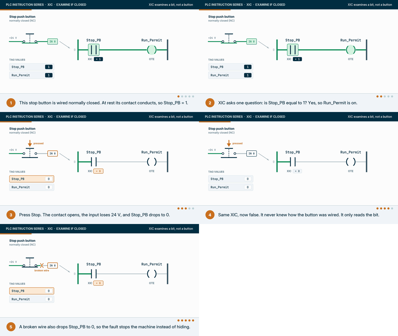
Stops are wired normally closed for a practical reason. If the wire breaks, a terminal backs out or the input loses power, the bit drops to 0 and the machine stops. A normally open stop wired to an XIO would do the opposite: a broken wire would look exactly like “nobody is pressing Stop”, and the machine would keep running with a dead stop button. Treat that as engineering practice that applies to any stop or permissive signal. It covers one kind of failure, an open circuit. A wire shorted to 24 V, a welded contact or a stuck input channel still reads 1, which is one reason an emergency stop is never just a PLC input: it belongs to a safety relay or safety controller with its own diagnostics.
So the rule I use, and teach, is to pick the instruction from the value the bit has when the rung should pass:
| Field device and wiring | Bit when the rung should pass | Instruction |
|---|---|---|
| Start button, normally open | 1 only while pressed | XIC |
| Stop button, normally closed | 1 while not pressed | XIC |
| Air pressure switch, closed when pressure is above setpoint | 1 while pressure is OK | XIC |
| Motor overload contact, normally closed | 1 while healthy | XIC to run, XIO to raise the trip alarm |
| Photo-eye, output on when it sees a part | 1 while a part is present | XIC for “part here”, XIO for “lane clear” |
| Low-level float, made when the level is above it | 1 while there is liquid | XIC as a pump permissive |
Notice that the instruction column is almost all XIC, even though the devices are a mix of normally open and normally closed. That is the point. XIO appears where the rung should pass on a 0: a fault bit that is 0 when healthy, a “lane clear” check, or an alarm on a lost signal.
The photo-eye row hides a trap worth naming. An XIO for “lane clear” also passes when the sensor dies or its wire breaks, because a dead sensor reads 0 too. Where a false “clear” could cause a collision, choose a sensor mode where failure reads as blocked, or add a sensor diagnostic.
One honest caveat. A standard input card cannot tell a broken wire from a pressed normally closed button; both read 0. Some diagnostic input modules can detect an open wire on each point. On an ordinary card, the wiring choice is what turns an open circuit into a stop, not the logic.
XIC vs XIO: what is the difference?
XIC and XIO test the same bit and give opposite answers to that test. XIC, Examine If Closed, is true when the bit is 1. XIO, Examine If Open, is true when the bit is 0. If the rung coming into either one is false, both pass false. Neither changes the bit. Use XIO when the rung should pass because something is absent, off or not faulted.

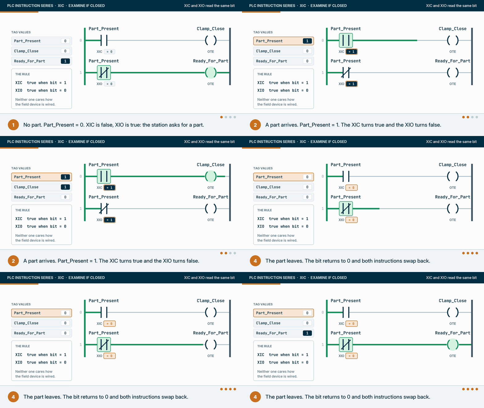
| XIC (Examine If Closed) | XIO (Examine If Open) | |
|---|---|---|
| True when the bit is | 1 | 0 |
| Symbol | Two bars | Two bars with a slash |
| Other vendors’ name | Normally open contact | Normally closed contact |
| Structured text equivalent | IF Bit THEN | IF NOT Bit THEN |
| Typical use | Permissives, running and ready signals, normally closed stops | Fault-free conditions, “lane clear”, alarms on lost signals |
| Changes the bit | No | No |
Remember the bit, not the switch.
How do XIC instructions combine? Series is AND, parallel is OR
Two XICs in series pass power only if both bits are 1, which is a logical AND. Two XICs on parallel branches pass power if either bit is 1, which is a logical OR. Almost every permissive chain and every “start from here or from there” rung in a plant is built from these two shapes.

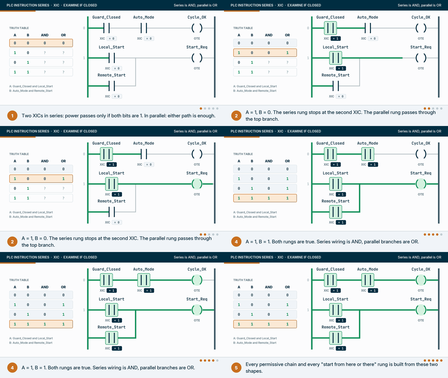
| A | B | Series rung: A AND B | Parallel rung: A OR B |
|---|---|---|---|
| 0 | 0 | 0 | 0 |
| 1 | 0 | 0 | 1 |
| 0 | 1 | 0 | 1 |
| 1 | 1 | 1 | 1 |
In the animation, A is Guard_Closed on the series rung and Local_Start on the parallel rung; B is Auto_Mode and Remote_Start.
Two things follow from this. First, for plain XIC and XIO instructions on bits that do not change mid-scan, the order in a series chain does not change the answer, so put them in the order a technician would check them, with the most likely blocker first. Second, an XIC is not limited to the left side of a rung. It can sit anywhere an input instruction is allowed, including inside a branch after other instructions.
When does an XIC look at its bit? The scan, prescan and asynchronous I/O
An XIC reads its bit at the moment the controller executes that instruction, each time its routine runs (normally once per scan). What value it finds depends on when the bit was last written. In a classic scan, inputs are copied into memory at the start and do not change until the next scan. In a Logix controller, input data arrives on its own schedule and can change mid-scan.

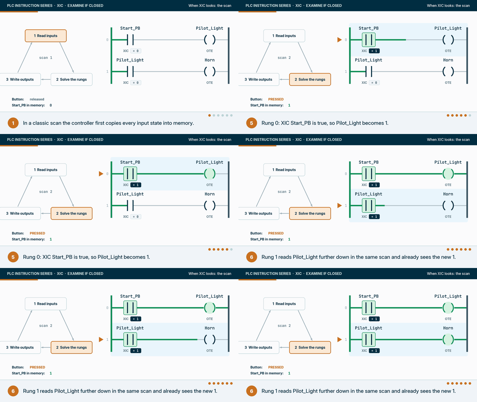
Process image controllers: one snapshot per scan
Siemens documents this model for the S7-1500 in its cycle and response times function manual: at the start of each cycle the CPU reads the input modules into the process image of the inputs, then runs the user program, then writes the process image of the outputs to the output modules. Every XIC on an input read through the process image sees the same snapshot for the whole scan. (Siemens also allows direct peripheral reads, written with a :P suffix, which bypass the image; ordinary logic rarely needs them.) The SLC 500 works the same way, with an input scan before the program scan.
The animation shows the consequence. A button pressed halfway through a scan is invisible until the next one, which at typical scan times of a few to a few tens of milliseconds nobody notices. Internal bits are different: when rung 0 writes Pilot_Light, an XIC on Pilot_Light in rung 1 sees the new value in the same scan, because it is reading memory the program just changed. A rung above the writer sees it one scan later, which is exactly why a seal-in contact turns true on the scan after its coil.
Logix controllers: inputs update on their own schedule
ControlLogix and CompactLogix controllers do not take one snapshot per scan. Rockwell’s ControlLogix 5590 user manual describes I/O data as refreshed asynchronously to logic execution: each module sends its data at its requested packet interval (RPI), or sooner on a change of state where the module is configured for it, and the input tags change whenever that data arrives. Outputs go to the modules on the same asynchronous basis. An input tag can therefore change between two rungs that read it in the same scan.
Most of the time that does no harm. It bites when two rungs must agree. If rung 10 starts a sequence step on Part_Present and rung 40 latches the step’s data on the same tag, the two can see different values in one scan. The usual fix is to buffer: copy the input words you care about into internal tags once, at the start of the task, with a synchronous copy (CPS) or a single move of the whole word so a higher-priority task cannot interrupt it halfway, and have every XIC read the copies. I treat buffering as a design decision for each program, not a rule for every input. High-speed or event-driven signals often belong in their own handling instead.
Prescan and level, not edge
Two more behaviours come straight from the execution table. During prescan, when the controller goes into Run, XIC passes false regardless of its bit. Output coils (OTE) on those rungs are cleared for that pass; latched bits (OTL) keep their values. And XIC is level-sensitive: it is true on every scan while the bit is 1. If you want something to happen once when a button is pressed, XIC alone will do it on every scan the button is held. That is the job of a one-shot instruction (ONS) or a transition-sensing contact, which gets its own post in this series.
XIC in practice: eight scenarios from simple to advanced
These scenarios run from the first rung most people learn to patterns I’d expect to see in a well-built plant program. Each one shows the rung in a particular state, why XIC is the right instruction there, and what tends to go wrong. Tag names are examples, written the way I’d want them in a real program.
1. Material handling: start and stop with a seal-in
The classic motor circuit, the PLC version of three-wire control. Start is a normally open button, Stop is normally closed, and the coil’s own bit holds the rung in after Start is released. Every instruction on the rung is an XIC. The overload and other permissives are left out to keep the rung readable; a real one has them in series with Stop.

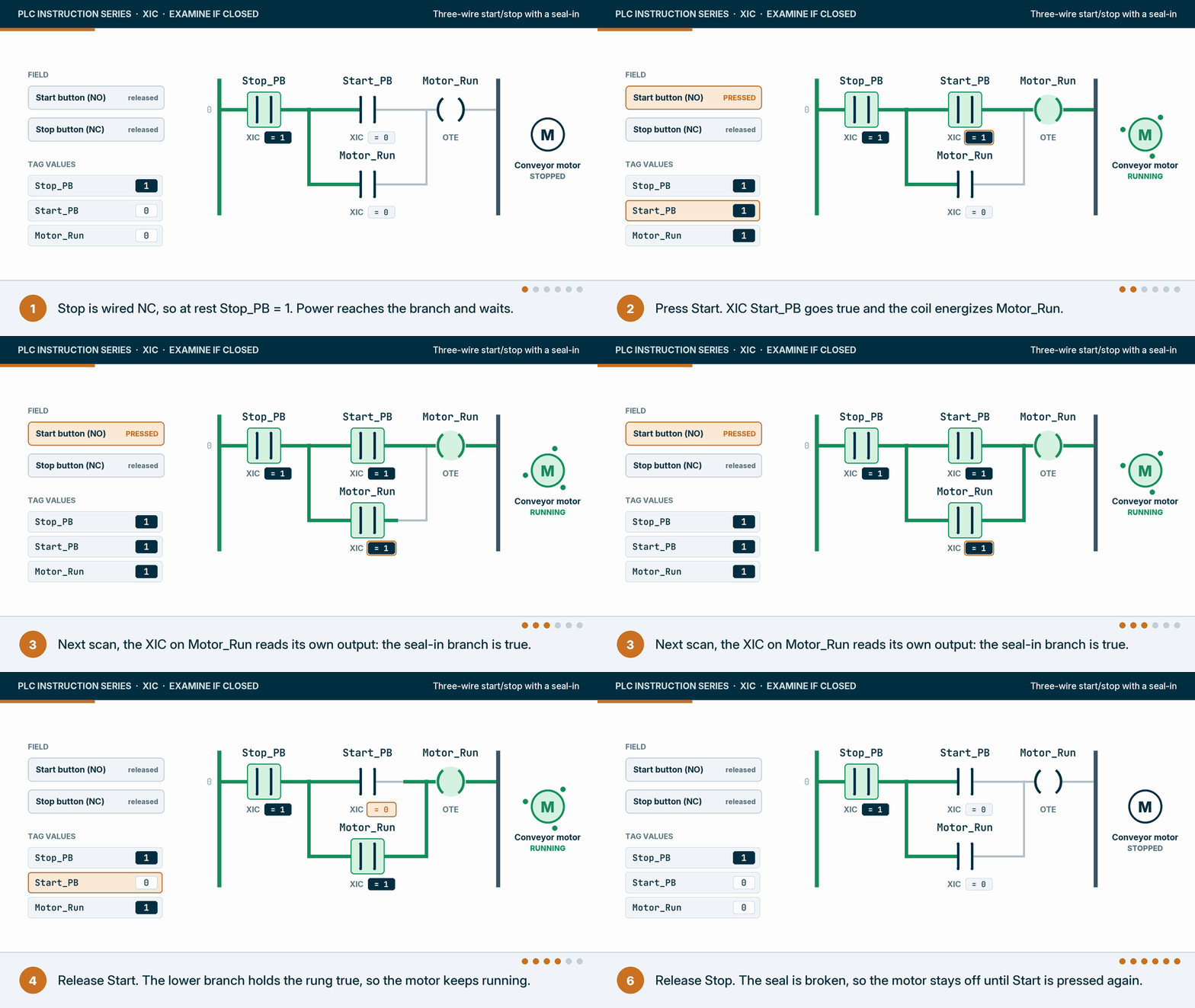
Why XIC: each bit is 1 in the state that should let the motor run: Stop at rest, Start while pressed, and the motor’s own run bit once it is on. What goes wrong: a stop button wired normally open and programmed as XIO, which keeps running after a broken wire. And note what this rung seals on: its own coil bit, which is a command, not proof the motor is running. Where the starter has an auxiliary contact, many programs seal on that feedback instead, so a tripped starter breaks the seal.
2. Packaging: a labeler fires only when four conditions agree
A label applicator should only fire when the conveyor is running, a product is at the photo-eye, the labeler reports ready, and there is no labeler fault.
Why XIC: Conveyor_Running, Product_At_Eye and Labeler_Ready are all 1 in the state where the labeler should fire. Labeler_Fault is 0 when healthy, so it takes an XIO. What goes wrong: because XIC is level-sensitive, this rung holds Label_Request at 1 for as long as the product sits at the eye. If the labeler acts on the level rather than an edge, one product can get two labels. In a real program the request goes through a one-shot or the labeler’s own handshake.
3. Water and wastewater: pump down between two float switches
A lift station pump should start when the level reaches the high float and keep running until the level falls below the low float. That is the seal-in pattern again, with floats instead of buttons.
Why XIC: the low float is made, so its bit is 1, while there is liquid above it, which is exactly when the pump may run. The high float only needs to start the pump; the Pump_Run branch holds it. What goes wrong: without the seal-in branch the pump starts and stops on every ripple at the high float. If a float’s wiring fails open, this rung stops the pump, which is safe for the pump but not for the wet well, so real stations add a separate high-high alarm and often a backup float circuit outside the PLC.
4. Chemicals and brewing: a high level switch raises an alarm and stops the fill
A batch tank fills through an automatic inlet valve. A high level switch, LSH-101, sits near the top of the tank and closes when the liquid reaches it. One bit does two jobs on two rungs: an XIC on it raises the alarm, and an XIO on the same bit takes the permit away from the inlet valve.

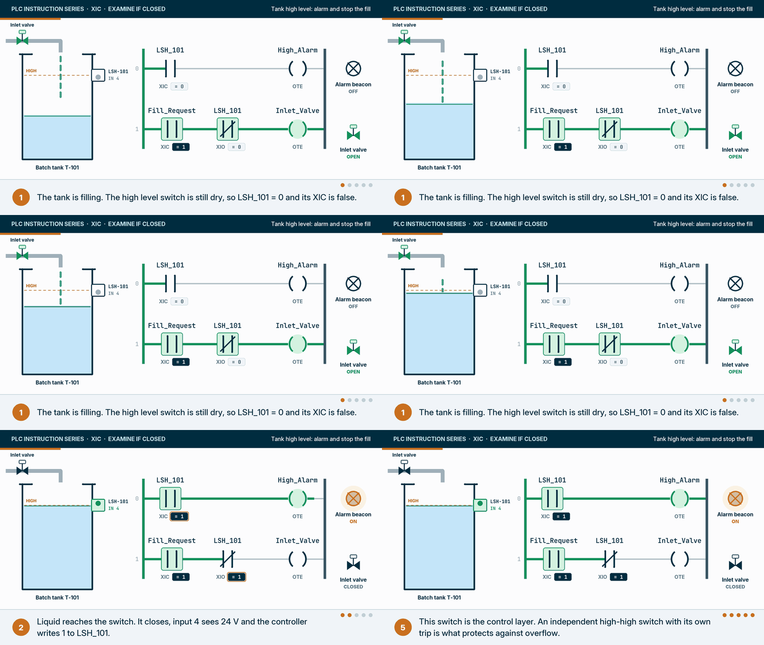
Why XIC: the alarm should be on exactly when the switch bit is 1, and that is the question XIC asks. What goes wrong: three things. First, the wiring. Many plants wire level switches fail-safe, so the contact is closed while the level is normal and opens on a high level or a broken wire. Then the bit is 1 when all is well, and the alarm rung needs an XIO, which is this post’s main rule again: read the loop drawing before you choose. Second, chatter. Liquid sloshing at the switch makes and breaks it, so the alarm flickers and the valve cycles. Latch the alarm until an operator acknowledges it, and do not restart the fill on the switch alone: wait for a drain-down delay or a lower level reading, from a second switch or a level transmitter, and a fresh fill request. Third, layers. This switch and these rungs are ordinary process control. Protection against an overflow that could hurt someone or the environment belongs to an independent high-high switch with its own trip, designed as a safety instrumented function to IEC 61511, the process-industry safety standard, where the hazard calls for one, never to the same switch and the same rung.
5. Food and beverage: a CIP supply pump starts only on a proven route
In a clean-in-place system the supply pump should only run when the program is in the supply step and the valves for one valid route have proven their positions with their own feedback switches.
Why XIC: each proof bit is 1 when the valve has reached the commanded position, which is the condition the pump needs. Series XICs make “both valves of this route”, parallel branches make “this route or that one”. What goes wrong: reading the valve’s command bit instead of its proof switch. An XIC on the command tells you what the program asked for, not where the valve is, and that difference is exactly what a route proof exists to catch.
6. Pharmaceutical: a cleanroom airlock never opens both doors at once
An airlock between two cleanroom grades has two doors, and only one may be open at a time so air never flows straight through. Each door’s release rung needs the other door proven closed.
Why XIC: Door_B_Closed is 1 only while door B’s position switch proves it is shut, which is exactly the condition door A needs before its lock may be released. What goes wrong: two things. Reading the lock command instead of the door position switch is the same command-versus-proof trap as the CIP route; door position stays the proof. And as drawn, if both doors are closed and both requests arrive in the same scan, both rungs are true and both doors are released together. The usual fix is a cross-interlock: add an XIO on Door_B_Release to rung 3 and an XIO on Door_A_Release to rung 4, so whichever rung is solved first wins: here door A, because rung 3 runs before rung 4. The cross-interlock reads the other door’s release command only to break a tie inside one scan. This is the program-side interlock; the door hardware usually has its own, and an emergency release must never depend on this logic.
7. Bottling: one bit of a status word from an OEM filler
Machines from other builders usually report their state as a status word over the network, and their interface specification says what each bit means. XIC can read a single bit inside a DINT directly.
Why XIC: Filler_Status.4 is the filler’s own “ready” bit; writing .4 reads bit 4 of that DINT without copying it anywhere. What goes wrong: bit numbering that starts at 1 in the builder’s document while Logix starts at 0, byte and word order on the network, and bit numbers that drift between machine software versions (keep the builder’s interface document under the same change control as the program, and if a builder will not share it, the options are the same as for a PLC program the OEM won’t hand over), and status words that stop updating when the connection drops while still holding their last value. A rung like this should sit behind a communication-health check, usually a heartbeat bit the other machine toggles and this controller watches with a timer.
8. Assembly cell: standard logic reads the safety system, it does not perform it
A robot cell will not start unless the safety relay is healthy, the gate is closed and the robot is home. The XIC on Safety_Relay_OK is the one people misunderstand.
Why XIC: each bit is 1 in the state where a cycle may begin. What goes wrong, and this one matters: treating this rung as the safety function. The safety function lives in the safety relay or a safety controller, designed and validated to the performance level the risk assessment requires: ISO 12100 for the risk assessment, ISO 10218 for the robot cell, and ISO 13849-1 for the performance level. The standard PLC reads the relay’s status so it can sequence the cell and tell the operator why it will not start. If removing this rung would make the cell unsafe, the design is wrong, not the rung.
What does XIC look like in each vendor’s software?
Every PLC programming environment that offers ladder has the instruction. Rockwell Automation calls it XIC in both RSLogix 500 and Studio 5000 Logix Designer (more on how we work with those platforms on our Rockwell Automation page); Siemens, Mitsubishi Electric, Schneider Electric and Omron call it a normally open contact, and CODESYS-based software calls it a contact. The symbol is the same everywhere. What changes is the operand: a tag name, an absolute address, or a device number.
| Vendor | Software | Name of the instruction | Example operand | Text form |
|---|---|---|---|---|
| Rockwell Automation | Studio 5000 Logix Designer (ControlLogix, CompactLogix) | XIC, Examine If Closed | Start_PB, Local:1:I.Data.0 | Rung text XIC(Start_PB); ST IF Start_PB THEN |
| Rockwell Automation | RSLogix 500 (SLC 500, MicroLogix) | XIC, Examine If Closed | I:0/4, B3:3/14 | XIC I:0/4 |
| Siemens | TIA Portal (S7-1200, S7-1500) | Normally open contact | "Start_PB", %I0.0 | SCL IF "Start_PB" THEN; STL A "Start_PB" on S7-1500 only |
| Mitsubishi Electric | GX Works3 (MELSEC iQ-R, iQ-F) | Normally open contact | X0, M0 | MELSEC mnemonics: LD X0 starts a rung, AND X1 adds one in series |
| Schneider Electric | EcoStruxure Control Expert (Modicon M580) | Normally open contact | A named BOOL or EBOOL variable, or a %I address | ST IF Start_PB THEN |
| Omron | Sysmac Studio (NJ/NX) | Normally open contact | A named BOOL variable | ST IF Start_PB THEN |
| IEC 61131-3 / CODESYS | CODESYS-based software, including EcoStruxure Machine Expert | Contact | A named BOOL variable | ST IF Start_PB THEN |
| AutomationDirect | CLICK Programming Software | Normally open contact | X001, C1 | None; ladder only |
Sources: Rockwell Automation 1756-RM003 and 1747-RM001; Siemens STL for S7-1500 online help; CODESYS online help; AutomationDirect CLICK online help; Phoenix Contact PLCnext Engineer help for the IEC 61131-3 contact definitions.
The same contact in each vendor’s editor
This is what the instruction looks like on screen in 26 programming environments from 18 vendors. They are ordered by how often you are likely to meet them: first the platforms that dominate North American plants (Rockwell Automation, Siemens, Omron, AutomationDirect, Schneider Electric and Mitsubishi Electric, which top Control Design’s readers’ choice ranking), then the machine-builder platforms you find on imported equipment, then regional and compact controllers. Each screenshot comes from the vendor’s own help or manuals or from a published tutorial, credited under it, and every one is framed the same way with the instruction ringed in amber. Pick a tab to switch software. Notice how little the symbol changes and how much the operand does: a tag with an alias, a file address, a named variable with a %I address, a device number, a plain-English name with spaces.
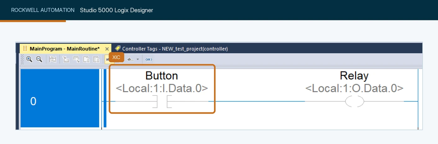
Button, an alias for the first input point of local slot 1, Local:1:I.Data.0. The project is offline, so the contact is drawn grey with no power flow. Screenshot: Control.com, Intro to PLC Programming with Rockwell's Studio 5000 and CompactLogix.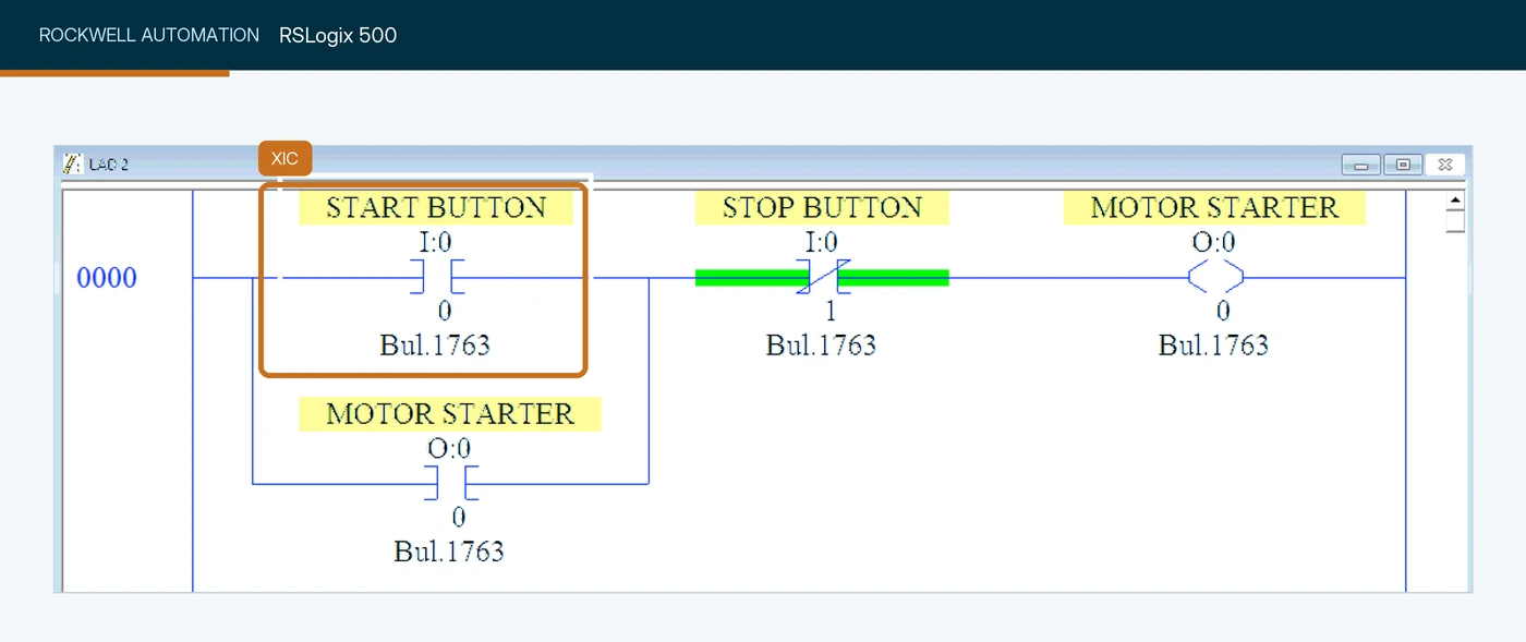
I:0/0, the start button, with the address written as the file I:0 over the bit number. The seal-in contact below it is also an XIC. Screenshot: SolisPLC, PLC Programming Fundamentals: XIC Instruction.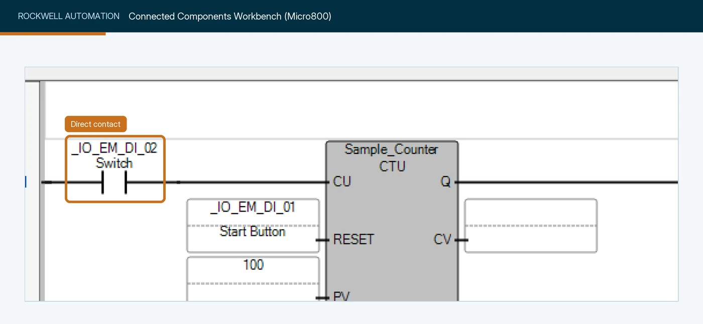
_IO_EM_DI_02, aliased Switch, counting into a CTU. Micro800 uses IEC 61131-3 instruction names, so you will not see the XIC mnemonic here even though it is a Rockwell Automation controller. Screenshot: Control.com, Tutorial: First Program Using Rockwell's Micro800 Series PLC.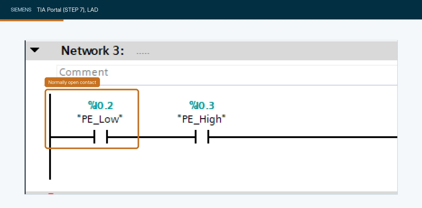
"PE_Low" (%I0.2) and "PE_High" (%I0.3). Siemens shows the symbolic name and the absolute address together. Screenshot: SolisPLC, Siemens TIA Portal Programming Example: Basic Ladder Logic Instructions.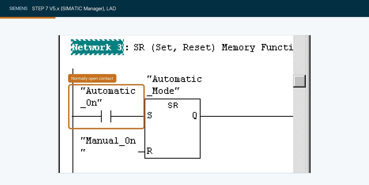
"Automatic_On" setting an SR flip-flop. Plenty of S7-300 and S7-400 plants still run this classic editor. Screenshot: Siemens, Programming with STEP 7 manual.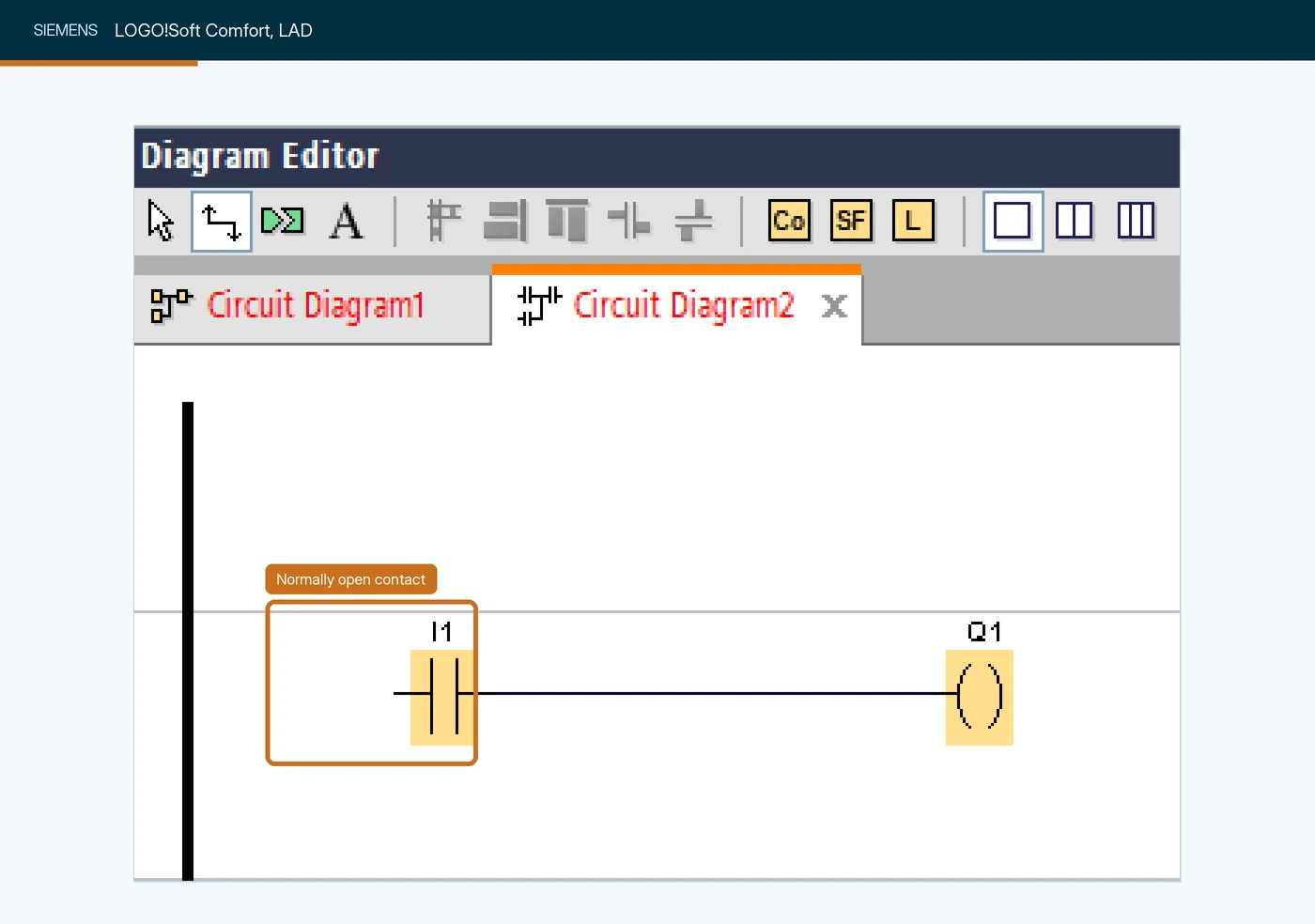
I1 driving output Q1. LOGO! numbers its inputs and outputs from 1, with no byte and bit. Screenshot: SolisPLC, Siemens LOGO! PLC Training: How to Get Started with LOGO! Soft Comfort.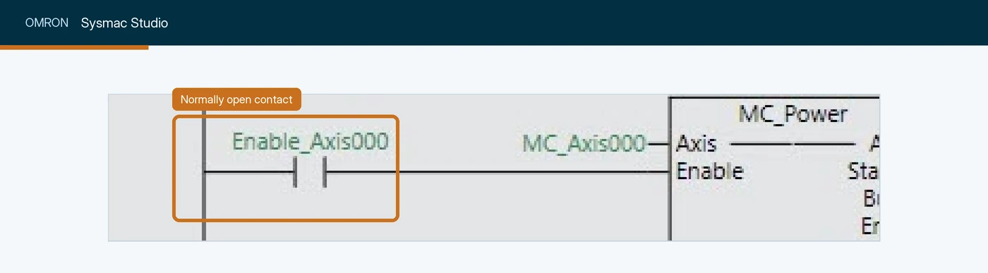
Enable_Axis000 feeding the Enable input of an MC_Power motion block. Sysmac programs use named variables throughout. Screenshot: Omron Europe Automation Knowledge Base, Using 3D Simulation in Sysmac Studio.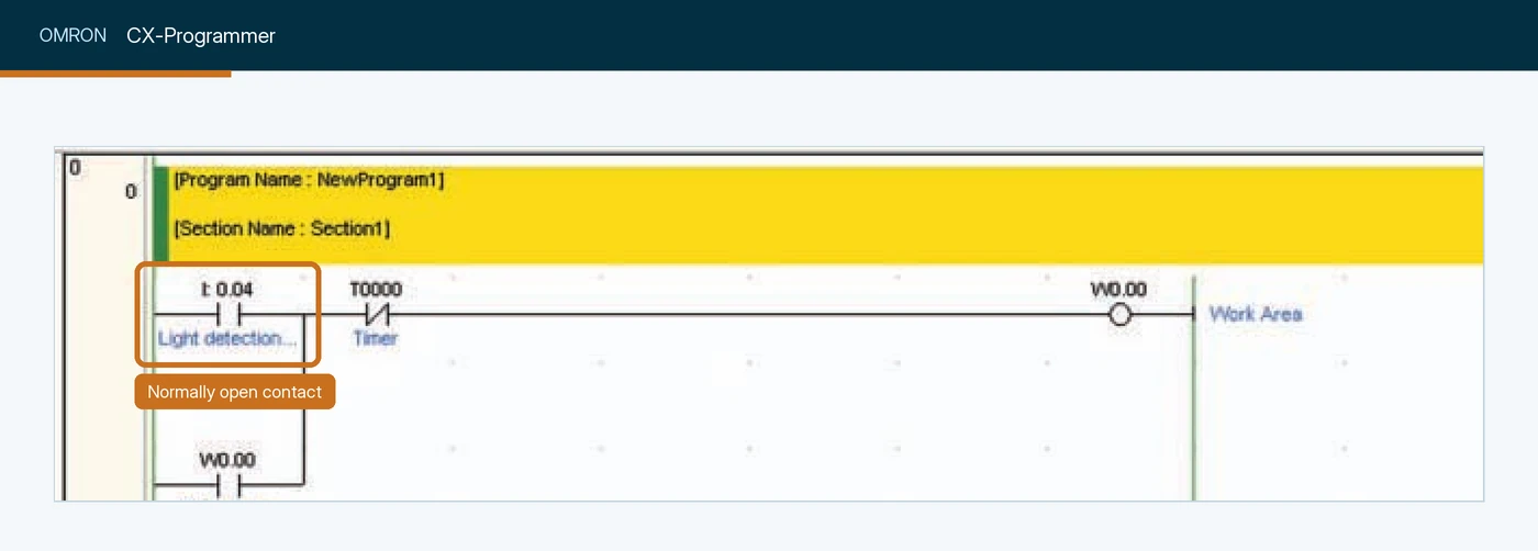
0.04, commented Light detection, in series with a normally closed timer contact T0000 and sealed in by W0.00. CX-Programmer addresses are channel and bit, not names. Screenshot: Omron, CP1L/CP1E CPU Unit Introduction Manual (W461).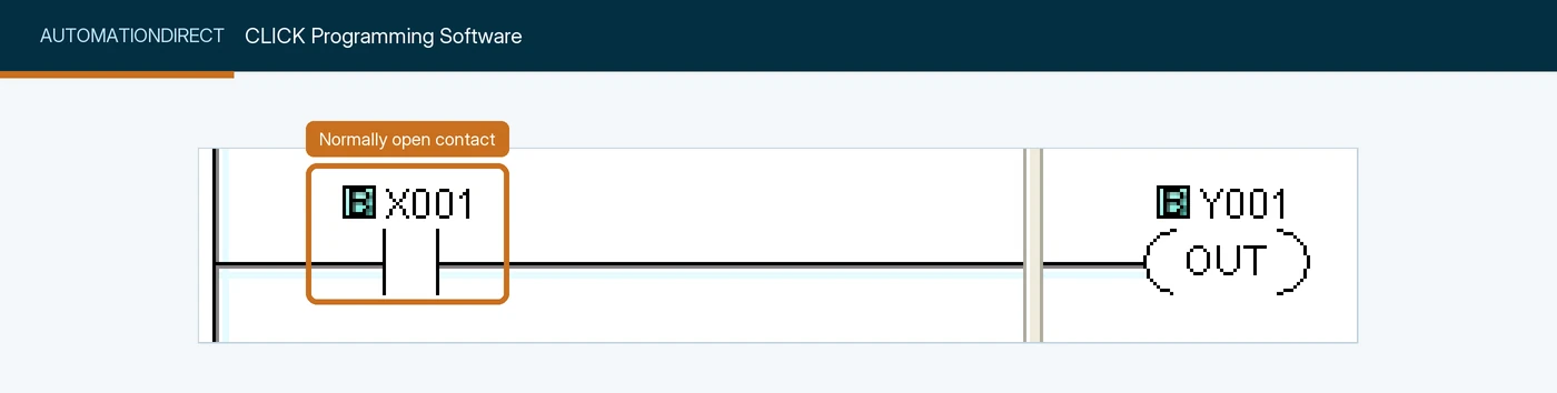
X001 driving the output Y001. The free CLICK software is one of the easiest ways to practise ladder at home. Screenshot: AutomationDirect CLICK online help, Normally Open Contact.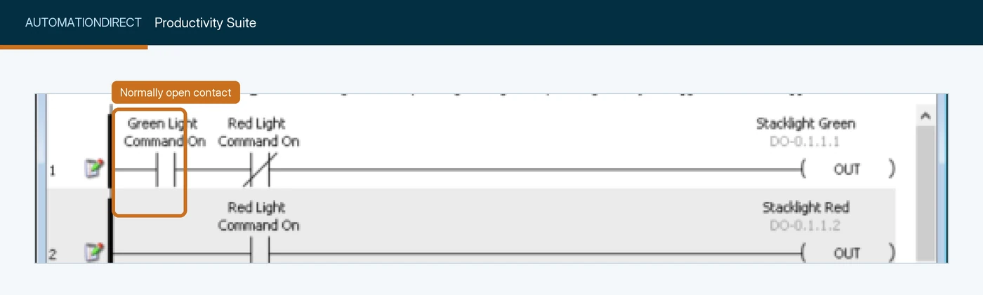
Green Light Command On in series with a normally closed contact, driving Stacklight Green. Productivity tags are plain-English names, spaces included. Screenshot: AutomationDirect, Productivity Suite online help.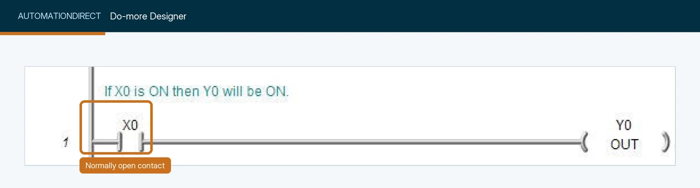
X0 driving output Y0, under a plain-language rung comment. Screenshot: AutomationDirect, Do-more Designer help, Contact - Normally Open.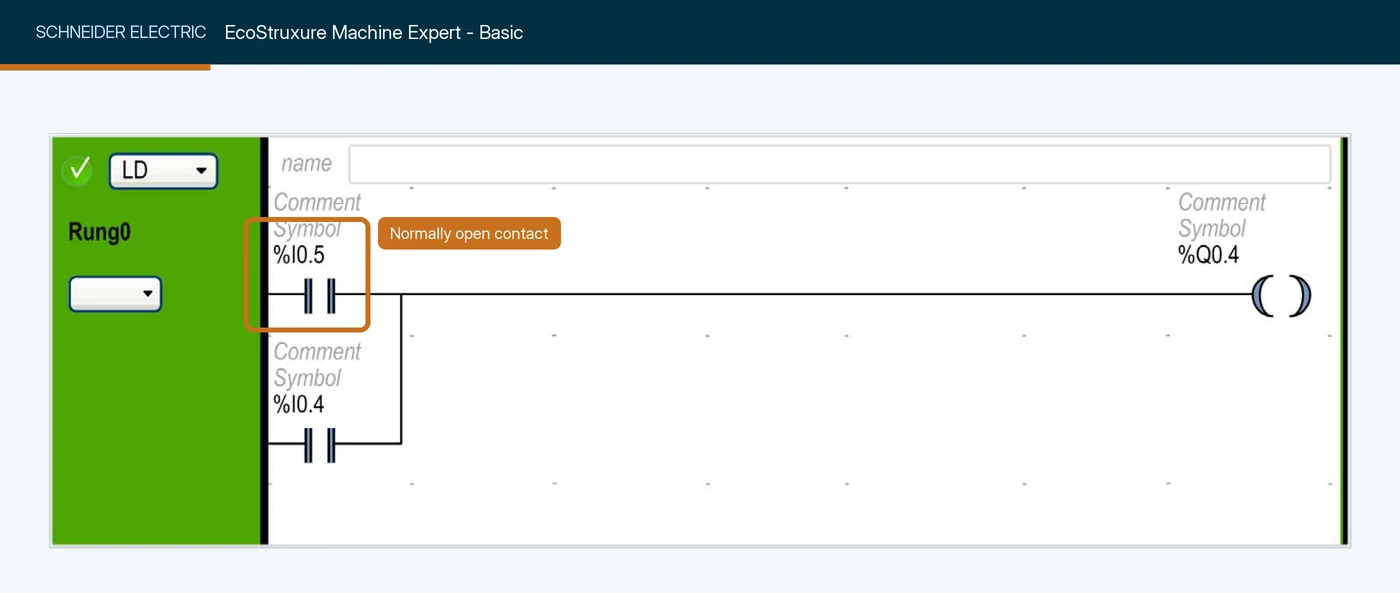
%I0.5 and %I0.4 in parallel, driving %Q0.4. Each contact has room for a symbol and a comment above the address. Screenshot: Schneider Electric, EcoStruxure Machine Expert - Basic Operating Guide.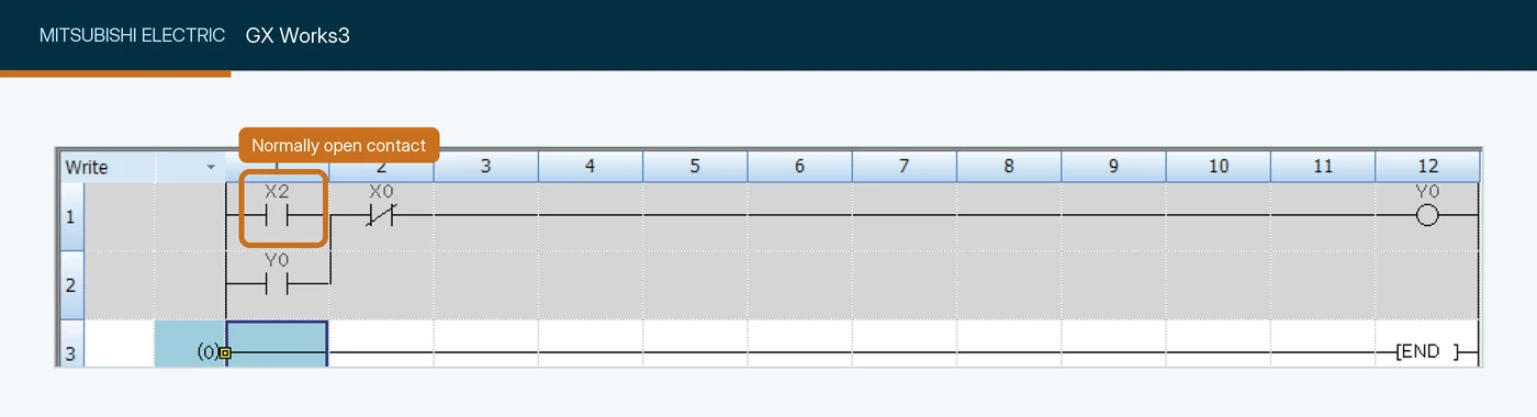
X2, in series with a normally closed contact on X0, driving Y0, with a Y0 contact below as the seal-in. Mitsubishi operands are device numbers, not names. Screenshot: Mitsubishi Electric, FX5U training manual.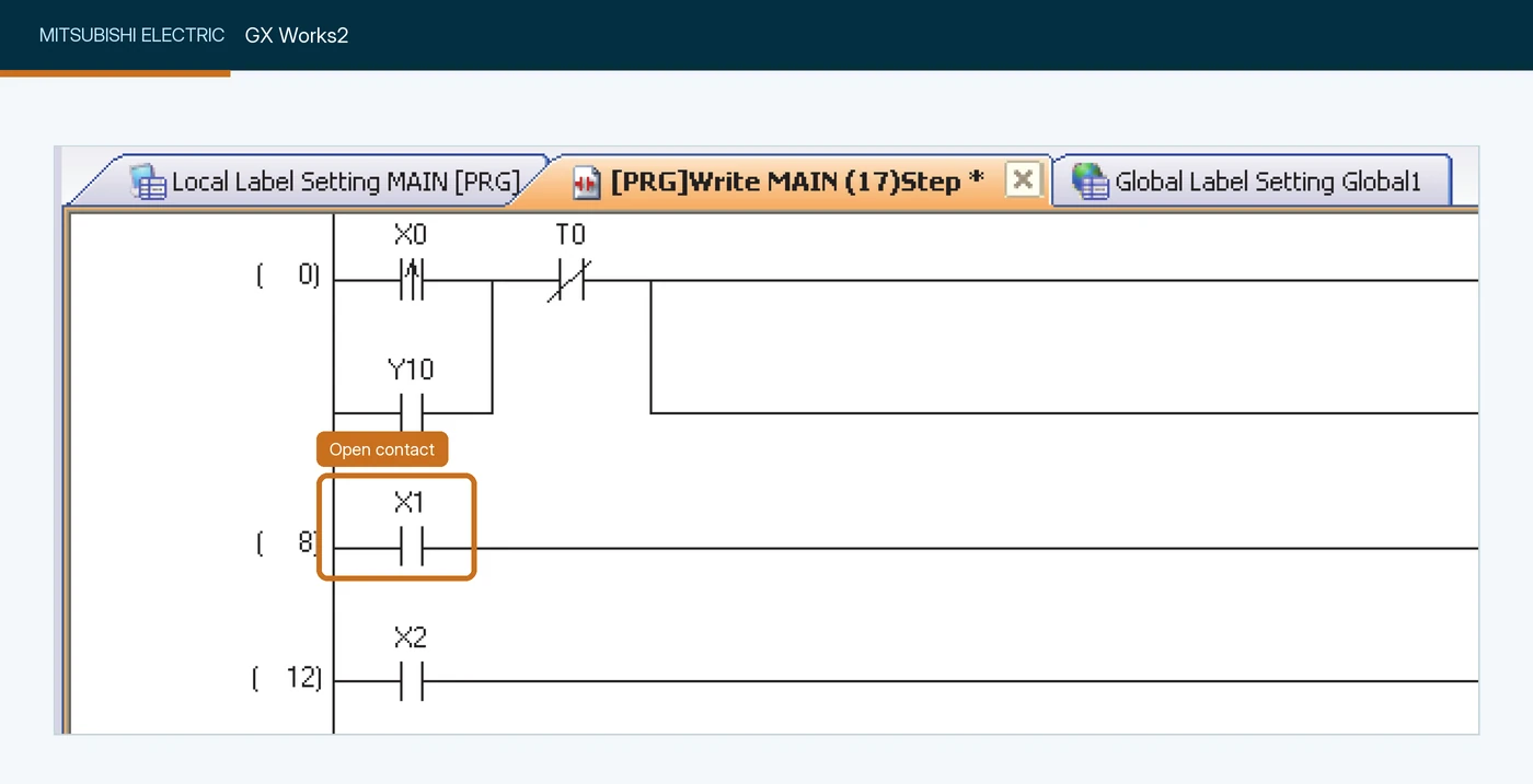
X1. The X0 contact above it carries an arrow because it is a rising-edge contact, a different instruction. Screenshot: Mitsubishi Electric, GX Works2 Beginner's Manual (Simple Project).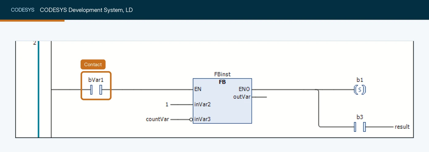
bVar1 enabling a function block. CODESYS-based software, including Schneider Electric EcoStruxure Machine Expert, calls this element simply a contact. Screenshot: CODESYS online help, Programming in the LD editor.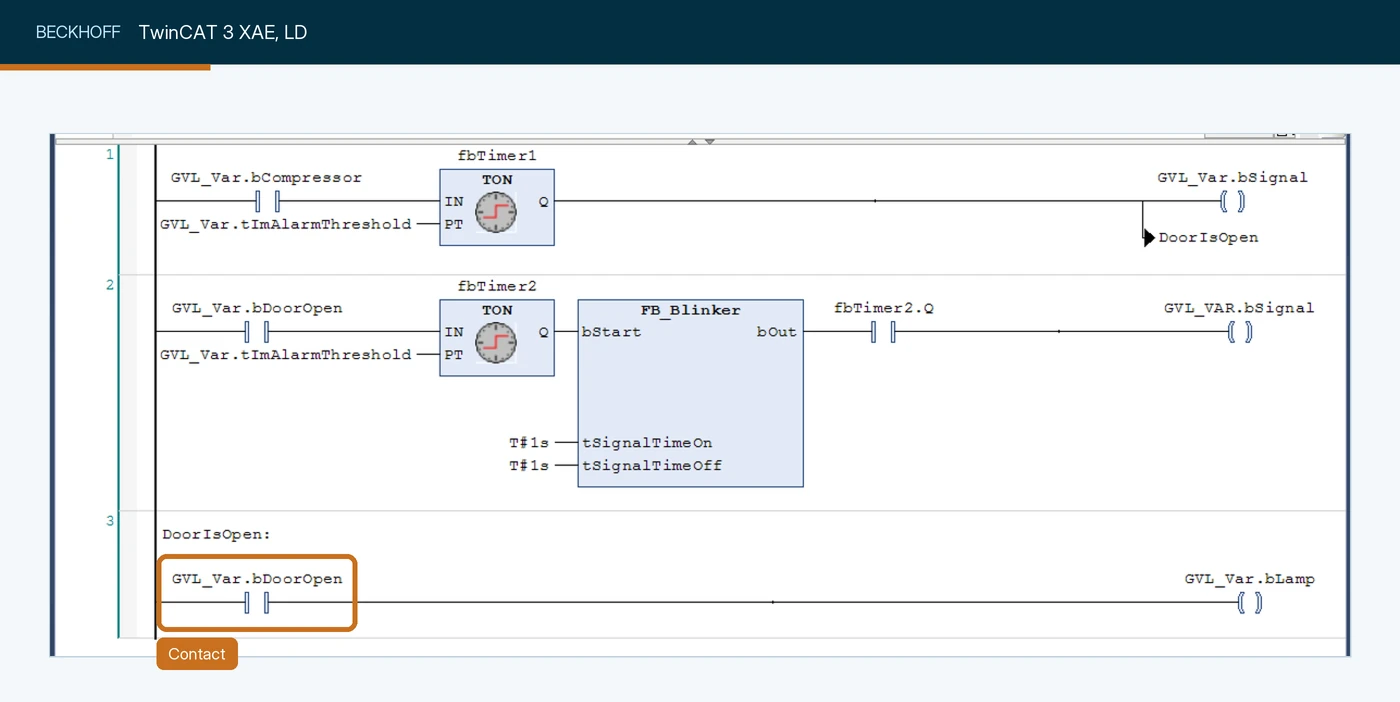
GVL_Var.bDoorOpen driving GVL_Var.bLamp, in a network carrying the jump label DoorIsOpen. TwinCAT, like other CODESYS-family editors, calls the element simply a contact. Screenshot: Beckhoff Information System, Your first TwinCAT 3 PLC project.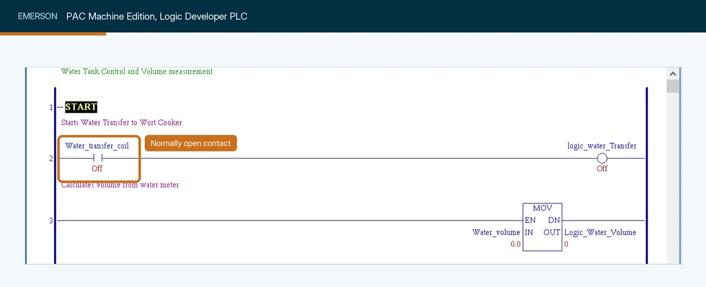
Water_transfer_coil, monitored, so its current value (Off) is shown under it. Screenshot: Emerson, PAC Machine Edition Logic Developer PLC Getting Started Guide (GFK-1918).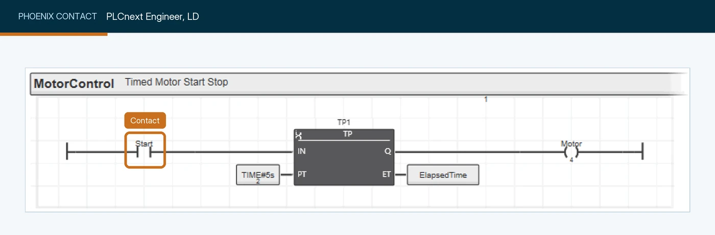
Start triggering a TP pulse timer that drives Motor. Screenshot: Phoenix Contact, PLCnext Engineer online help.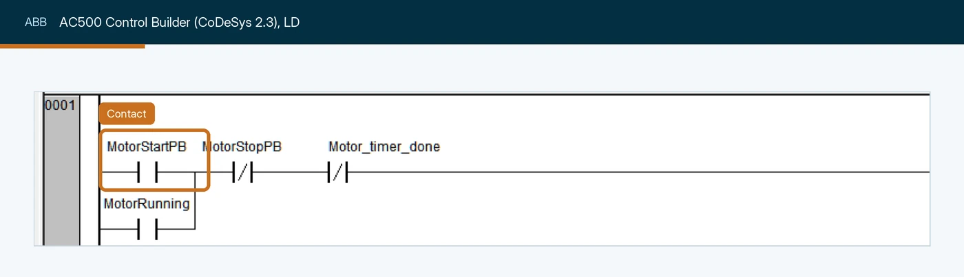
MotorStartPB with a seal-in contact on MotorRunning. Screenshot: ABB, AC500 eCo PLC First Project application note.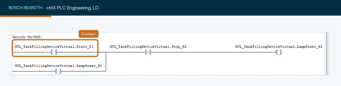
Start_S1 with a seal-in on LampPower_H1, the same three-wire pattern as scenario 1. Screenshot: Bosch Rexroth Automation Community.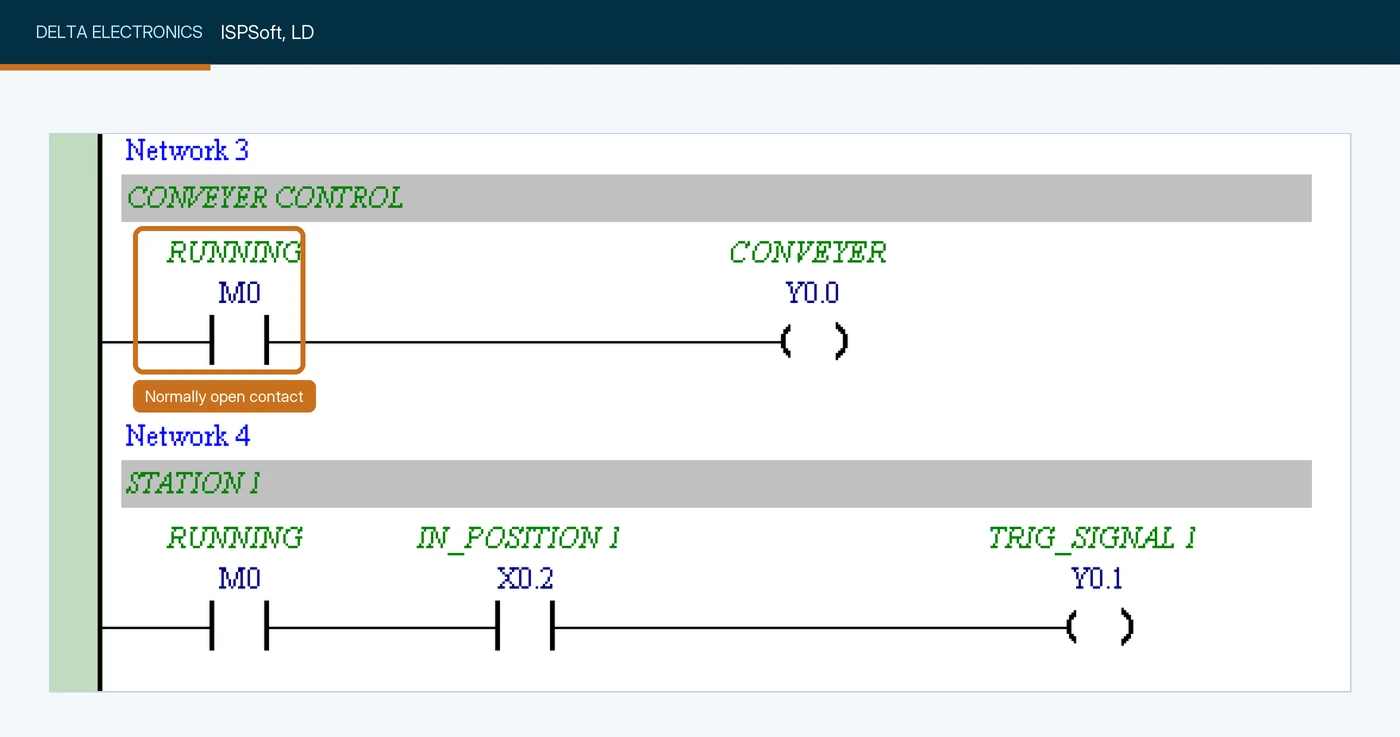
M0, symbol RUNNING, driving output Y0.0. Screenshot: Delta Electronics, ISPSoft User Manual.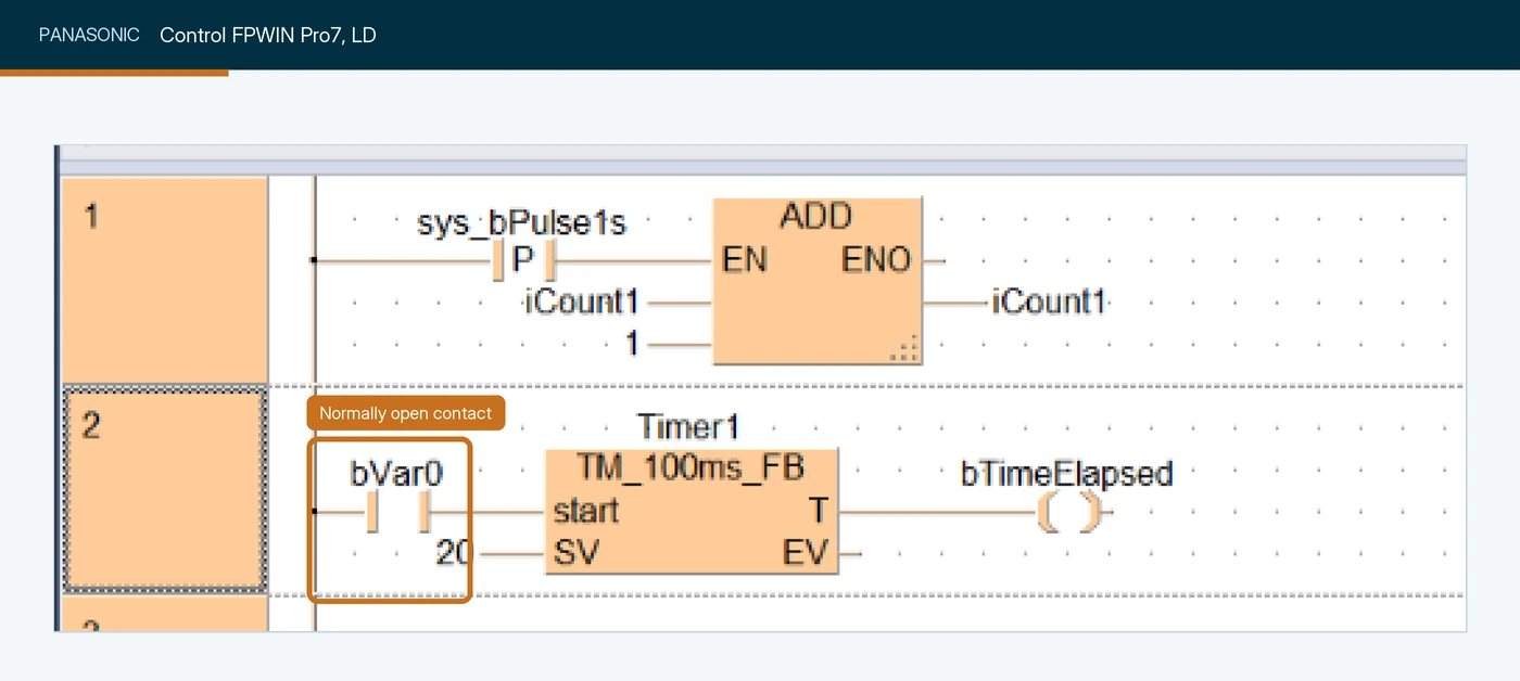
bVar0 starting a 100 ms timer. Screenshot: Panasonic Industry, Control FPWIN Pro7 online help.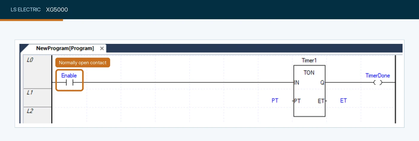
Enable starting the TON timer Timer1. Screenshot: LS Electric XG5000 help, hosted by AutomationDirect.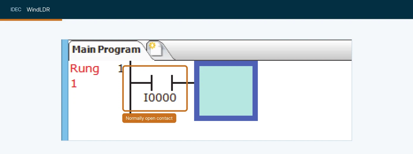
I0000, the first element placed on a new rung. Screenshot: IDEC, FC6A Series MicroSmart LAD Programming Manual.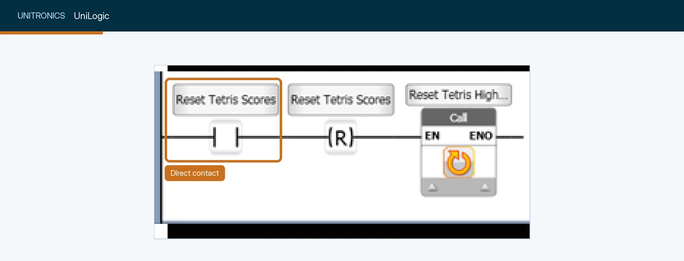
Reset Tetris Scores driving a reset coil. UniLogic's generated code calls this element a direct contact. Screenshot: Unitronics, UniLogic help.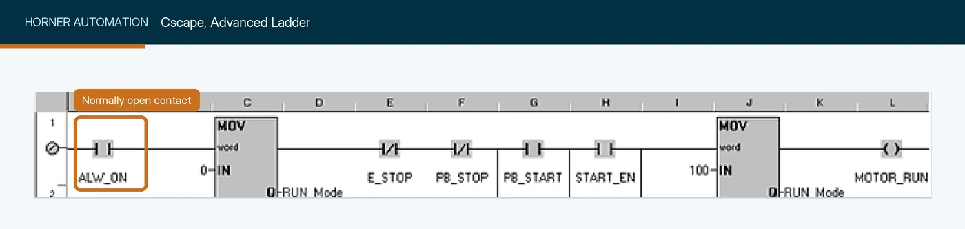
ALW_ON, a system bit that is always on, enabling a MOV. Screenshot: Horner Automation, Cscape help.A few platforms are missing because we could not find a public screenshot of their ladder editor showing the contact. We searched each vendor’s online help and manuals and the published tutorials:
| Vendor | Software | Why it is not shown yet |
|---|---|---|
| Schneider Electric | EcoStruxure Control Expert (Modicon M340, M580) | The Control Expert manuals could not be retrieved from Schneider Electric’s site and no public copy shows the LD editor. The Machine Expert - Basic and CODESYS screenshots above show Schneider Electric’s other two editors. |
| KEYENCE | KV STUDIO | The manuals sit behind a download form and no public screenshot of the ladder editor turned up. |
| B&R | Automation Studio | No public screenshot of the LD editor, and B&R’s training modules could not be retrieved. |
| WAGO | e!COCKPIT | No public LD screenshot. e!COCKPIT is built on CODESYS, so its editor looks like the CODESYS one above. |
| Inovance | InoProShop, AutoShop | The public manuals have no ladder editor figures. InoProShop is also built on CODESYS. |
If you work in one of these, the instruction is the same normally open contact; we will add your editor when we capture it ourselves.
Sources for the ordering: Control Design 2023 readers’ choice awards for North America, and the ABI Research 2023 PLC competitive ranking for global reach. Neither publishes market share percentages, so we do not quote any.
Two differences are worth knowing before you switch platforms. Siemens describes its logic in terms of the result of logic operation (RLO): on an S7-1500, the STL A instruction checks an operand for 1 and ANDs it with the current RLO (the first check in a string simply loads it), which is the same series AND shown above. The S7-1200 has no STL at all, so there you work in LAD, FBD or SCL. And the MELSEC instruction mnemonics make the rung structure explicit, with LD to start a rung and AND and OR for series and parallel contacts, where Rockwell keeps that structure in the drawing.
If you are setting up a practice environment, I have walked through installing RSLogix 500 for free and TIA Portal for PLC programming in earlier posts.
Why won’t my XIC go true? A debugging checklist
When an XIC is not doing what you expect, the instruction itself is almost never wrong. The bit is not what you think it is, or the rung around it is not what you think it is. Work through the chain from the rung back to the field, in order, and stop at the first link that disagrees.
- Check the rung to its left. XIC can only pass true if the rung condition reaching it is true. A false instruction further left looks like a dead XIC.
- Look at the bit itself. Online, check the tag’s value in a tag monitor, not only on the rung. Make sure it is the same tag in the same scope: a program-scoped tag with the same name as a controller-scoped one is a classic trap.
- Check whether the routine is being scanned. An XIC in a routine that no JSR calls, or in a task that is inhibited, shows its last state and never changes.
- Follow the alias. Confirm which physical point the alias tag points at. A swapped alias is a five-minute fix that can take a day to find.
- Check the module and its connection. A faulted module or a lost I/O connection can leave an input tag holding a stale value. Check the module’s fault status before trusting the tag.
- Check the input card’s indicator. If the input’s status light is off, the problem is in the field: the device, the wiring, the fuse or the supply. If the light is on but the bit is 0, the problem is between the card and the tag: the module, the connection, the alias or a force.
- Look for a force. A forced bit holds its value whatever the field does. Most programming software flags forces prominently; check that flag before trusting what you see.
- Find every writer. Cross-reference the tag. If an OTE, an HMI or another controller also writes it, the value you see is whoever wrote last.
- Think about timing. A pulse shorter than the input filter or the update interval may never reach the tag, and a pulse shorter than the scan can reach the tag and still be missed, because the XIC only looks once per scan. For signals like that, use a latching or high-speed input module, a high-speed counter, or an event task.
Cross-referencing is the step people skip and the one that finds the most problems. It is also one of the reasons a written program standard and version control for PLC code pay for themselves: a tag with one writer is a tag you can reason about.
Common XIC mistakes
| Mistake | What happens | Fix |
|---|---|---|
| Choosing XIC or XIO from the switch label | Stop buttons and permissives behave backwards | Choose from the value the bit has when the rung should pass |
| Normally open stop button programmed with XIO | A broken wire looks like “not pressed”; the machine cannot be stopped from that button | Wire stops normally closed and use XIC |
| Expecting XIC to act once | The action repeats every scan while the button is held | Use a one-shot (ONS) or a transition contact |
| Reading a command bit as if it were feedback | The rung trusts what the program asked for, not what the device did | XIC on the proof switch or the status bit |
| Using a standard PLC rung as the safety function | Safety depends on code that was never designed or validated for it | Safety relay or safety controller; the PLC reads status only |
| Two rungs reading a fast-changing Logix input | They disagree inside one scan | Buffer the input word once at the start of the task, with CPS |
Test yourself: an interview quiz on XIC
Ten questions, the kind I'd ask in an interview for a controls role to see whether someone really understands XIC. Pick an answer and the explanation appears straight away.
0 of 10 answered
In one sentence, what does an XIC instruction test?
XIC reads a bit in memory. For a physical input that bit is a copy of the terminal state made by the I/O system, but the instruction itself never looks at the terminal or the switch.
A stop button is wired normally closed and nobody is pressing it. What is the value of its input bit?
At rest a normally closed contact is closed, so the input sees voltage and the bit is 1. The program has no say in the bit's value; it only decides how to read it.
Same stop button, still not pressed. An XIC on its bit is:
The bit is 1, so the XIC is true and the rung can pass. Pressing Stop drops the bit to 0 and the XIC goes false. That is why stops are almost always XIC on a normally closed button.
Why are stop buttons usually wired normally closed?
With a normally closed stop, losing the circuit for any reason (a pressed button, a broken wire, a blown fuse) drops the bit to 0 and stops the machine. A normally open stop with a broken wire simply never stops it.
Two XIC instructions in series on one rung behave like:
Power has to pass through both, so both bits must be 1. Parallel branches give OR.
An XIC's bit is 1, but an instruction to its left on the same rung is false. What does the XIC pass to the right?
An XIC can only pass true if the rung reaching it is true. This is the first thing to check when an XIC looks dead.
The same bit is 0. What do an XIC and an XIO on that bit each give, with a true rung coming in?
XIC is true when the bit is 1; XIO is true when the bit is 0. They give opposite answers to the same test.
An operator holds a button for two seconds and the scan time is 10 ms. On how many scans is the XIC on that button true?
XIC is level-sensitive: it is true on every scan while the bit is 1. To act once per press you need a one-shot (ONS) or a transition-sensing contact.
What does Siemens TIA Portal call the instruction Rockwell calls XIC?
Siemens TIA Portal and most other vendors' ladder editors call it a normally open contact; CODESYS-based software calls it a contact. The ladder symbol is essentially the same across all of them.
The tag
Guard_Closedreads 0 in the tag monitor, but the input's status light on the card is on. Where do you look next?A lit input light means the field side is delivering voltage. If the tag still reads 0, the problem sits between the card and the tag: the module and its connection, the alias, a force, or another writer.
That's the basics covered. If you'd like the next instruction in this series in your inbox, the sign-up is below. It's never needed to see an answer.
Five harder XIC problems
These are the kind of problems that separate someone who has read about XIC from someone who has commissioned with it. Each one gives you the situation and the task. Try it on paper before you open the solution. The rungs are written in Logix rung text: XIC(tag) and XIO(tag) are contacts, square brackets with commas are parallel branches, and OTE(tag) is the output coil.
Problem 1: seal in on the command or on the contactor?
A conveyor motor has a normally open Start button, a normally closed Stop button, an overload relay contact wired so that OL_OK is 1 while the overload is healthy, and a contactor auxiliary contact M1_Aux that is 1 when the contactor has pulled in. Write the run rung for M1_Run. It must start on Start, stop on Stop or an overload, and must not restart by itself when the overload is reset. Then decide what the seal-in branch should read: the command bit M1_Run or the feedback M1_Aux.
Show the solution
XIC(Stop_PB) XIC(OL_OK) [XIC(Start_PB) ,XIC(M1_Run) ] XIO(M1_Fault) OTE(M1_Run);Stop_PB and OL_OK are both 1 in the healthy state, so both are XIC in series. When the overload trips, OL_OK drops to 0, the rung goes false and M1_Run drops out, which breaks the seal. Resetting the overload brings OL_OK back, but the seal is already broken, so the motor waits for Start.
Seal on the command, and supervise the feedback separately. If you seal on M1_Aux alone, the contactor takes a few tens of milliseconds to pull in, and a quick tap on Start can be released before the feedback arrives, so the motor drops out. Feedback belongs in its own rungs: if M1_Run is 1 and M1_Aux stays 0 for longer than the contactor should take, a timer sets M1_Fault (failed to start); if M1_Aux drops while M1_Run is 1, that is an unexpected stop. The XIO on M1_Fault then takes the motor out until someone resets the fault. Timers get their own post in this series.
Problem 2: two rungs disagree about one input
In a ControlLogix program, rung 12 is XIC(Part_Present) OTE(Clamp_Close) and rung 47 is XIO(Part_Present) OTE(Request_Part). Part_Present is an alias for Local:2:I.Data.3, the module’s RPI is 2 ms, and the continuous task scans in about 18 ms. A few times a shift, the infeed sends a new part while the clamp is closing, and the trend shows Clamp_Close and Request_Part both at 1 at the end of the same scan. The rungs look mutually exclusive. Explain how this happens and fix it.
Show the solution
A Logix controller updates input tags asynchronously to the scan, every RPI, so Part_Present can change between rung 12 and rung 47 in the same scan. If the part leaves just after rung 12 runs, rung 12 saw 1 and closed the clamp, and rung 47 sees 0 and requests a part. Both outputs end the scan at 1.
Take one snapshot of the input at the start of the task and make every rung read the snapshot:
CPS(Local:2:I.Data, Inputs_Snap, 1);Then point both rungs at Inputs_Snap.3, or alias Part_Present to it. CPS copies the data in one operation that an I/O update cannot interrupt. For a single DINT a plain copy is already safe; CPS earns its place when you buffer several words that must agree with each other. Every rung after it now sees the same value for the whole scan, which is how a process image controller behaves on its own. Making the two outputs depend on each other (an XIO on Clamp_Close in the request rung) is also worth doing, because it states the rule you actually want: never request a part while the clamp is closing.
Problem 3: the OEM filler’s status word
A filler sends a 32-bit status word into the DINT Filler_Status. Its interface specification numbers the bits 1 to 32, says bit 5 is “Ready to receive”, and says bit 16 is a heartbeat that toggles every 500 ms. A colleague wrote XIC(Filler_Status.5) OTE(Infeed_Enable) and the infeed behaves strangely. Find the problem, then write rungs so the infeed only runs when the filler is ready and its communication is alive.
Show the solution
Logix numbers bits from 0, so bit 5 in a specification that counts from 1 is Filler_Status.4, and the heartbeat is Filler_Status.15. The colleague is reading bit 6 of the specification. Confirm the mapping on the running machine before trusting it: watch the bit change while the filler goes in and out of ready, and check byte and word order if the data passes through a gateway.
The heartbeat check needs two timers, one for each value the bit can get stuck at:
XIC(Filler_Status.15) TON(HB_High, 1500, 0);
XIO(Filler_Status.15) TON(HB_Low, 1500, 0);
XIO(HB_High.DN) XIO(HB_Low.DN) OTE(Filler_Comms_OK);
XIC(Filler_Status.4) XIC(Filler_Comms_OK) OTE(Infeed_Enable);
If the connection drops, the tag often keeps its last value rather than going to zero, depending on how the data arrives, so the ready bit can stay at 1. Do not rely on either behaviour: the heartbeat check works whichever way it fails. If the data comes through an I/O module or adapter connection, check that connection’s fault status as well. While the heartbeat toggles, neither timer reaches 1.5 s, three missed toggles. If the bit freezes at either value, one timer finishes, Filler_Comms_OK drops and the infeed stops even though the frozen ready bit still says 1. Filler_Comms_OK is true for the first 1.5 s after power-up, which does no harm because the ready bit is still 0 then.
Problem 4: a fail-safe high level alarm that needs acknowledging
The tank from scenario 4 has been rewired fail-safe: the level switch contact is closed while the level is normal, so LSH_101_OK is 1 when all is well and 0 on a high level or a broken wire. Write two rungs. High_Alarm must come on for a high level or a wiring fault and stay on after the level drops until an operator presses Alarm_Ack on the HMI to reset it, and acknowledging must not clear it while the level is still high. Inlet_Valve must close on the alarm and stay closed until the alarm is cleared.
Show the solution
[XIO(LSH_101_OK) ,XIC(High_Alarm) XIO(Alarm_Ack) ] OTE(High_Alarm);
XIC(Fill_Request) XIC(LSH_101_OK) XIO(High_Alarm) OTE(Inlet_Valve);
The first branch turns the alarm on while the condition is present, and nothing on that branch looks at Alarm_Ack, so acknowledging cannot clear an active alarm. The second branch is a seal-in that holds the alarm after the level drops, until Alarm_Ack breaks it. With fail-safe wiring the alarm reads the switch with XIO, not XIC: the rule from this post again, chosen by the value the bit has when the rung should pass.
A few details matter in practice. Make sure the HMI button is momentary, or clear Alarm_Ack in the program after it has been read. If it sticks at 1 the alarm still comes on, but it no longer latches: it follows the level, so a brief high level can come and go with nobody seeing it. And the XIO(High_Alarm) in the fill rung keeps the valve closed until a person has seen the alarm, which is usually what operations want after a high level. Once the alarm is reset and the level is below the switch, though, this rung reopens the valve if Fill_Request is still 1. Real systems usually also require a fresh fill request or a lower level reading first; that is left out here to keep the exercise on XIC and XIO. And an OTE seal-in does not survive a power cycle: if the alarm must, use OTL and OTU on a retentive tag.
Problem 5: the input light is on but the XIC is false
An XIC on Guard_Closed, on rung 20 of the routine Cell_Seq in the program Cell, shows 0 and the cell will not start. You collect these facts:
- The status light for input 6 on the module in slot 4 is on.
Local:4:I.Data.6is 1 in the tag monitor.- In Controller Tags,
Guard_Closedis a BOOL and its value is 1. - The cross reference for the controller-scoped
Guard_Closedshows one writer:XIC(Local:4:I.Data.6) OTE(Guard_Closed)in the routineMap_Inputsof the programMainProgram, which is scanned every cycle. - The
Cellprogram was imported from a sister line last month.
What is wrong, and how do you fix it and stop it happening again?
Show the solution
Facts 3 and 4 say the controller-scoped Guard_Closed is 1 and written correctly, yet the XIC shows 0. The XIC must be reading a different tag with the same name. In Logix, when a program has its own tag with the same name as a controller-scoped tag, the logic in that program uses the program tag. The import in fact 5 most likely brought a program-scoped Guard_Closed with it. Nothing writes it, so it sits at 0. Map_Inputs lives in a different program, so it still writes the controller tag; only the logic inside Cell is redirected to the program tag.
Open the Cell program’s tags, confirm the duplicate, check that nothing in that program needs it, then delete it so the routine binds to the controller tag. To prevent it, make import reviews check for program tags that shadow controller tags, and use a naming standard that makes scope obvious. This is step 2 of the debugging checklist above, and it is the reason that step exists.
Keep learning between posts
Sign up for The Plant-Side Brief, Joltek's free weekly email for controls engineers and technicians. Every answer on this page stays open whether you sign up or not.
Where XIC fits in this series
XIC is the first instruction in Joltek’s PLC Programming guide, where the instruction glossary lists every common instruction and links to each full page as it is published. It comes first because most of what follows depends on it: an output coil usually does nothing until a rung of XICs and XIOs decides whether it gets power. The next pages follow the order you meet these instructions in real programs: XIO, then the output coil OTE, latch and unlatch (OTL and OTU), then the one-shot, timers and counters.
If you are building or rebuilding your own PLC skills, the PLC scan cycle explained from the SCADA side is a good companion to the timing section above. And if your plant’s controls team needs this kind of grounding on its own equipment and programs, that is what our hands-on PLC and SCADA training for plant teams is for.
References and further reading
- Logix 5000 Controllers General Instructions Reference Manual (1756-RM003) · Rockwell AutomationExamine If Closed (XIC): operand, execution table, prescan and postscan.
- SLC 500 Instruction Set Reference Manual (1747-RM001) · Rockwell AutomationXIC and XIO in RSLogix 500, with input, output and timer done-bit examples.
- ControlLogix 5590 Controllers User Manual: Determine When I/O Data Is Updated (1756-UM900) · Rockwell AutomationI/O data is refreshed asynchronously to logic execution.
- STL for S7-1500: A, AND logic operation · Siemens, TIA Portal V20 online help
- SIMATIC S7-1500 Cycle and Response Times, Function Manual · SiemensThe process image of the inputs is read at the start of each cycle.
- CODESYS LD/FBD: Contact · CODESYS Group, online help
- LD Language Elements · Phoenix Contact, PLCnext Engineer helpNormally open, normally closed and transition-sensing contacts as IEC 61131-3 describes them.