
PLC Programming
XIO Instruction (Examine If Open): How It Works in a PLC
The XIO instruction is true when a bit is 0. How it works, when to use it, why it is not the normally closed button, XIO vs XIC, and 23 vendor editors.
Table of contents
The XIO instruction is the other half of every ladder program, and the half people get wrong more often. Its name, Examine If Open, invites the same mistake as XIC’s: reading it as a statement about a switch in the field, and reaching for it whenever a device is normally closed. XIO asks one question about one bit in memory: is this bit 0 right now? Choose it because the rung should pass when the bit is 0, and it becomes one of the most useful instructions you have. Choose it because the button is red and normally closed, and it will stop working exactly when you need it.
This page builds on the XIC instruction, which covers the bit-not-the-switch idea in depth. Here the focus is XIO’s own jobs: fault-free permissives, interlocks between machines, “nothing is in the way” checks, and the scan-order tricks that make an XIO useful. As with the XIC page, there is a quiz and five harder problems at the end, and every animation has a pause control.
The short version. XIO tests one bit: it is true when the bit is 0 and false when the bit is 1. Use it when the rung should pass because something is off, absent or not faulted. Remember that a bit also reads 0 when a wire breaks or nothing writes it, so never let an XIO be the only thing standing between a machine and a hazard.
What is the XIO instruction?
The XIO instruction, short for Examine If Open, is a ladder logic input instruction that checks one bit. If the rung reaching it is true and the bit is 0, XIO passes power to the next instruction. If the bit is 1, it blocks power. Rockwell Automation calls it XIO; most other vendors call the same symbol a normally closed contact, and CODESYS-based software calls it a negated contact.
The simplest useful XIO stops a machine when something is full. A bin has a switch that closes when the bin is full. While the bin has room the bit is 0, the XIO is true, and the feeder runs. When the bin fills, the bit becomes 1 and the feeder stops.

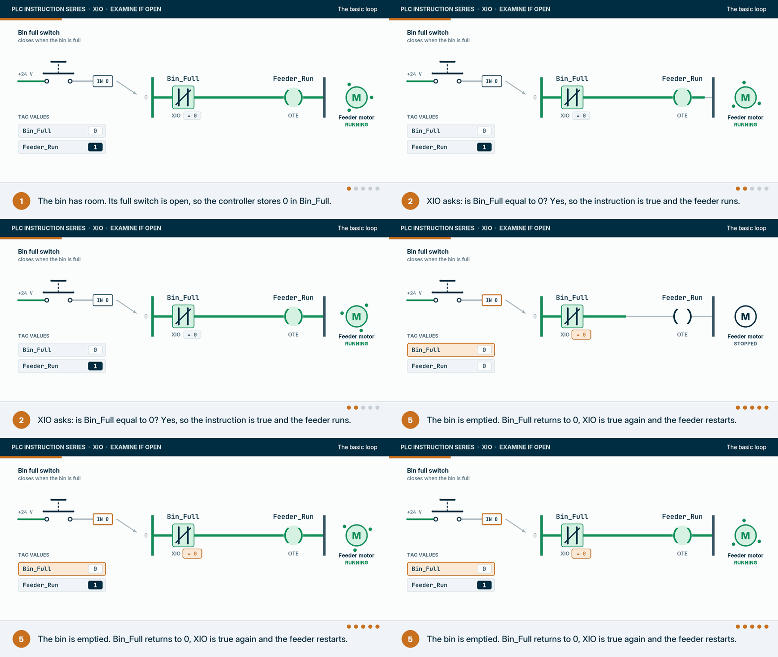
Rockwell’s Logix 5000 general instructions reference manual (publication 1756-RM003) defines XIO with one BOOL operand, the bit to be tested, and says it examines that bit to see if it is cleared. Its execution table is the whole instruction:
| Condition when the XIO executes | Rung condition passed to the right |
|---|---|
| Rung condition coming in is false | False |
| Rung condition coming in is true, bit is 0 | True |
| Rung condition coming in is true, bit is 1 | False |
| Prescan (when the controller enters Run mode) | False |
| Postscan | False |
Source: Rockwell Automation, Logix 5000 Controllers General Instructions Reference Manual, 1756-RM003, revision P, XIO section.
The same manual says XIO does not affect the arithmetic status flags and has no fault conditions. Its own example uses a limit switch bit and the overflow flag S:V: when the flag is cleared, there was no overflow, and the rung passes. There is no XIO in structured text; you write IF NOT Bin_Full THEN instead.
Why is it called “Examine If Open”?
For the same reason XIC is called Examine If Closed: the vocabulary comes from relay panels, where a contact really was open or closed. In a modern controller “open” means “the bit is 0”, nothing more. The XIC page tells that story; the one thing to carry over is the translation. Read every XIO as “true when the bit is 0” and the name stops misleading you.
The symbol carries the history too. XIO is drawn as a contact with a slash through it, the relay symbol for a normally closed contact. That is why so many people pair the slashed symbol with a normally closed device. The symbol describes the instruction’s logic, not the wiring outside the cabinet.
What does the XIO instruction actually read?
XIO reads a bit in controller memory, exactly as XIC does: a copy of an input terminal made by the I/O system, an internal bit, a member of a user-defined type, a timer’s status bit or one bit of a DINT. What makes XIO different is the value it passes on. A bit can be 0 for many reasons, and XIO is true for all of them.
- The field device is off or open. The normal case: the bin has room, the jam sensor sees nothing, the overload has not tripped.
- The signal is lost. A broken wire, a loose terminal or a blown fuse makes a signal that should be 1 read 0. An XIO on it turns true.
- Nothing writes the tag. A tag that no instruction, module or HMI writes keeps the value it was created with, which in practice is 0. An XIO on a misspelled or orphaned tag is true forever.
- Something else wrote 0. Another rung, a MOV, an HMI button or a recipe download.

The first case is the reason XIO exists. Cases two and three are the reason it needs care. As engineering practice: an XIC on a signal that is 1 when healthy goes false on a broken wire, which is the stop direction. An XIO on the same wire goes the other way: the rung goes true. That is fine when the XIO raises an alarm on a lost signal, which is one of its best uses. It is not fine when the XIO is the permissive that lets a machine move.
In RSLogix 500 the addressing changes but the instruction does not. Rockwell’s SLC 500 instruction set reference manual (1747-RM001) uses a normally closed motor overload contact wired to I:0/10 as one of its own XIO examples, alongside an output bit and a timer done bit. In Logix the operand can be any BOOL, written as a tag name such as Jam_Fault, a member such as Pump101.Fault, or a bit of a DINT such as Drive_Status.3.
Should you use XIO for a normally closed stop button?
No. A normally closed stop button holds its input at 24 V while nobody touches it, so its bit is 1 at rest. A rung that should let the machine run while Stop is not pressed must pass when the bit is 1, which is XIC. Programming it with XIO “because the button is normally closed” inverts the stop.

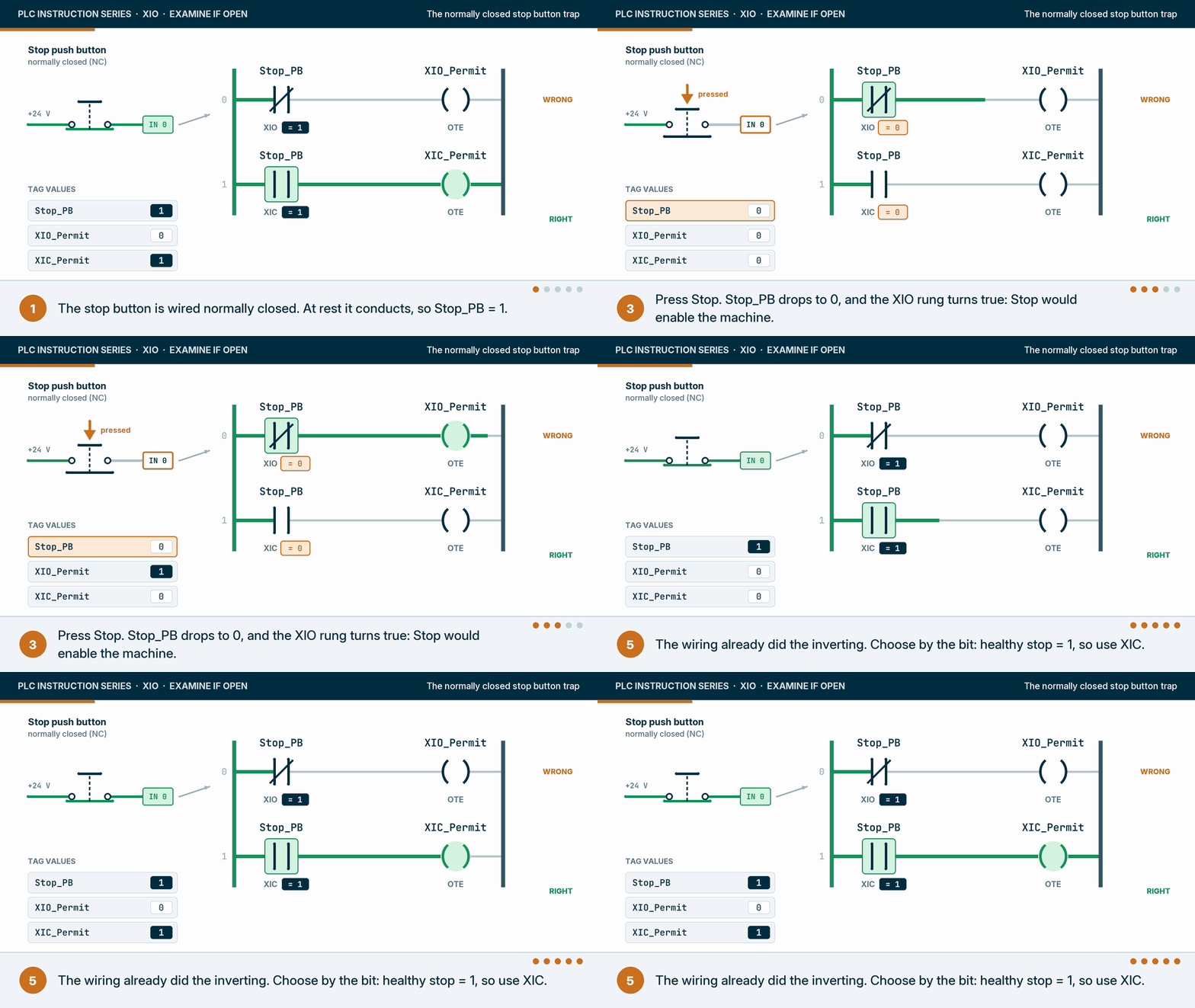
This is the most common XIO question, and the mistake behind it is double negation: the wiring already inverts the signal, so inverting it again in the logic cancels it out. The rule that avoids it is the same one the XIC page uses. Ignore the device type and ask what value the bit has when the rung should pass:
| Signal | Bit value when the rung should pass | Instruction |
|---|---|---|
| Stop button, normally closed, rung lets the machine run | 1 (not pressed) | XIC |
| Motor overload contact, normally closed, rung raises the trip alarm | 0 (tripped) | XIO |
| Fault bit set by the program, rung lets the machine run | 0 (no fault) | XIO |
| Photo-eye, on when blocked, rung releases the next carton | 0 (lane clear) | XIO |
| Other machine’s running bit, interlock rung | 0 (other machine stopped) | XIO |
| Low level switch, closed while wet, rung raises the low level alarm | 0 (dry) | XIO |
Notice where XIO appears: wherever the rung should pass because something is absent, stopped or healthy. That covers a lot of real logic, and none of it depends on whether the device is normally open or normally closed.
XIO vs XIC: what is the difference?
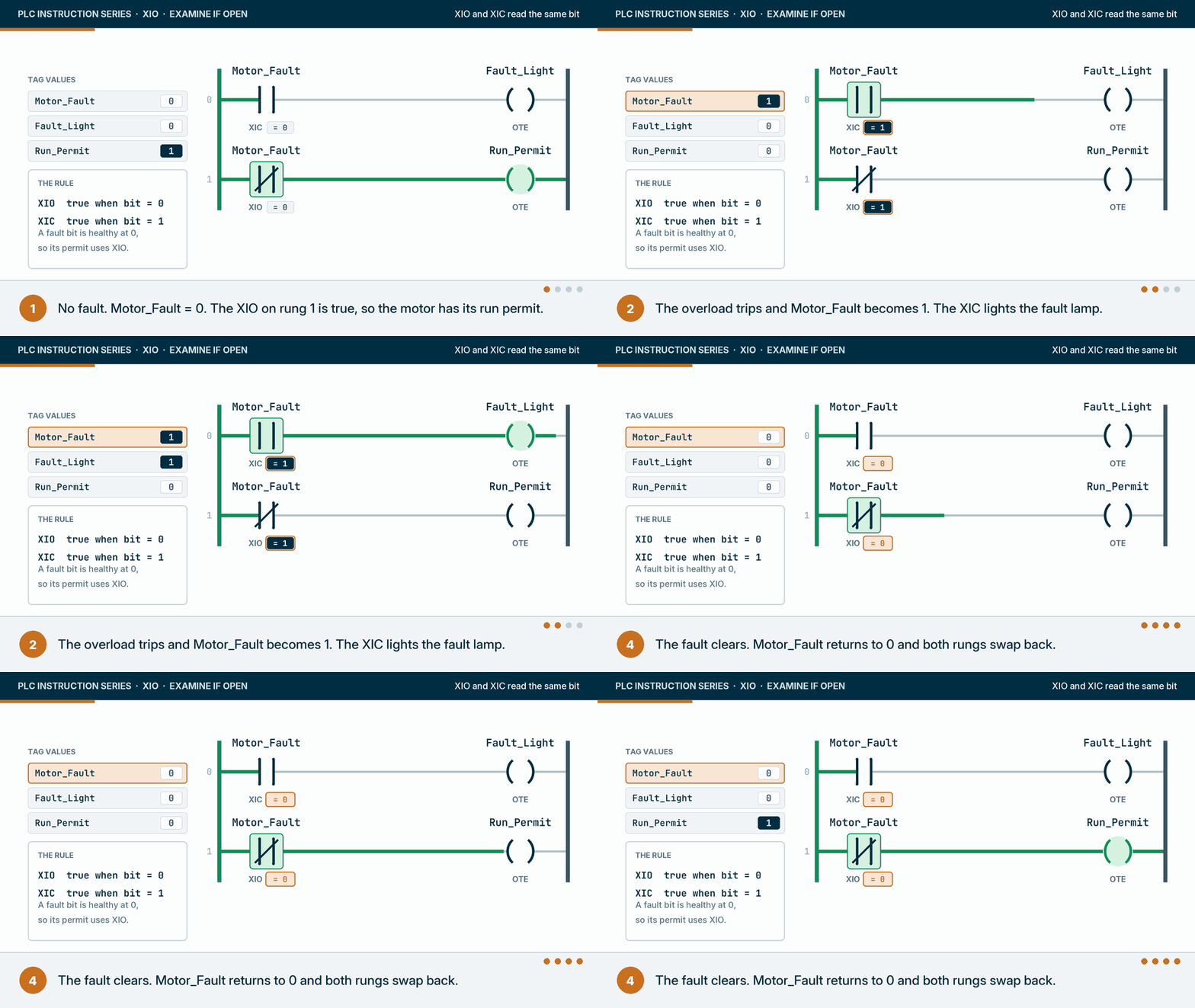
XIO and XIC test the same bit and give opposite answers. XIO is true when the bit is 0; XIC is true when the bit is 1. If the rung reaching either one is false, both pass false, and neither instruction changes the bit. Most programs read their important bits both ways, in different rungs.

| XIO (Examine If Open) | XIC (Examine If Closed) | |
|---|---|---|
| True when the bit is | 0 | 1 |
| Symbol | Two bars with a slash | Two bars |
| Other vendors’ name | Normally closed contact, negated contact | Normally open contact, contact |
| Structured text equivalent | IF NOT Bit THEN | IF Bit THEN |
| Typical use | No-fault permissives, interlocks, “lane clear”, alarms on lost signals | Running and ready signals, commands, normally closed stops |
| On a broken wire (signal 1 when healthy) it goes | True | False |
| Changes the bit | No | No |
The broken-wire row is the one to remember. It is why a permissive built from XICs tends to fail safe and one built from XIOs needs a second look.
How do XIOs combine in series and parallel?
XIOs in series pass power only when every bit is 0. XIOs in parallel pass power when at least one bit is 0. A chain of XIOs on fault bits is the usual “no faults at all” permissive: any single fault breaks it.

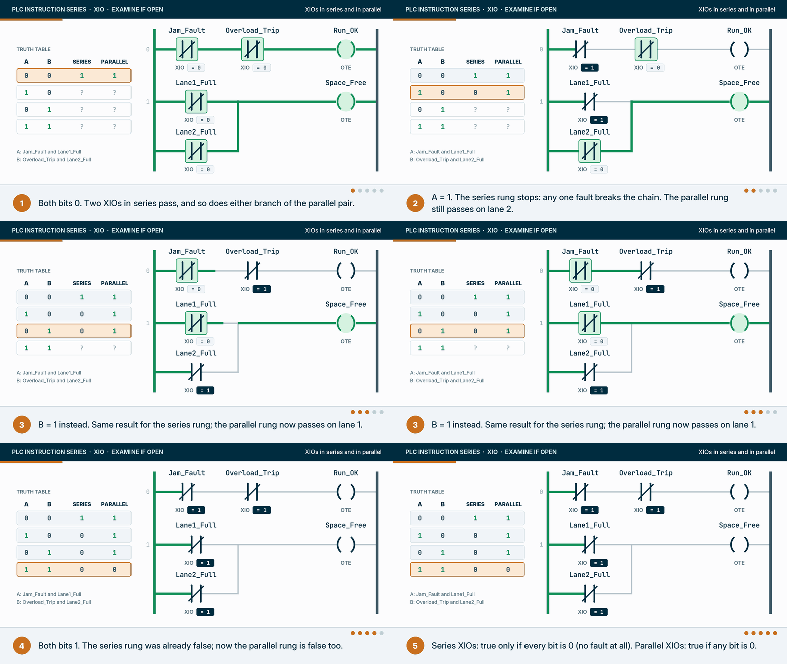
| A | B | Series XIOs: NOT A AND NOT B | Parallel XIOs: NOT A OR NOT B |
|---|---|---|---|
| 0 | 0 | 1 | 1 |
| 1 | 0 | 0 | 1 |
| 0 | 1 | 0 | 1 |
| 1 | 1 | 0 | 0 |
In the animation, A is Jam_Fault on the series rung and Lane1_Full on the parallel rung; B is Overload_Trip and Lane2_Full. Series XIOs are a logical NOR of the bits: true only when none is set. Parallel XIOs are a NAND: true unless all are set. Two useful consequences:
- One summary bit beats a long chain. A twelve-XIO permissive across a rung is hard to read online. Many programs build a single
Any_Faultbit from parallel XICs in one place and read it with one XIO everywhere else. The logic is the same (De Morgan’s law); the troubleshooting is far easier. - Parallel XIOs answer “is there room anywhere?” Two lanes, two full switches in parallel XIOs: the rung passes while either lane has space. That is the accumulation logic behind many packaging infeeds.
When does an XIO look at its bit? The scan and prescan
XIO reads its bit at the moment the controller executes it, so it sees whatever value the bit holds at that point in the scan. A bit written by a rung further down was last written in the previous scan, unless something outside this routine, such as an HMI or another task, changed it since. That timing is not a nuisance; it is how one of the oldest ladder patterns works.

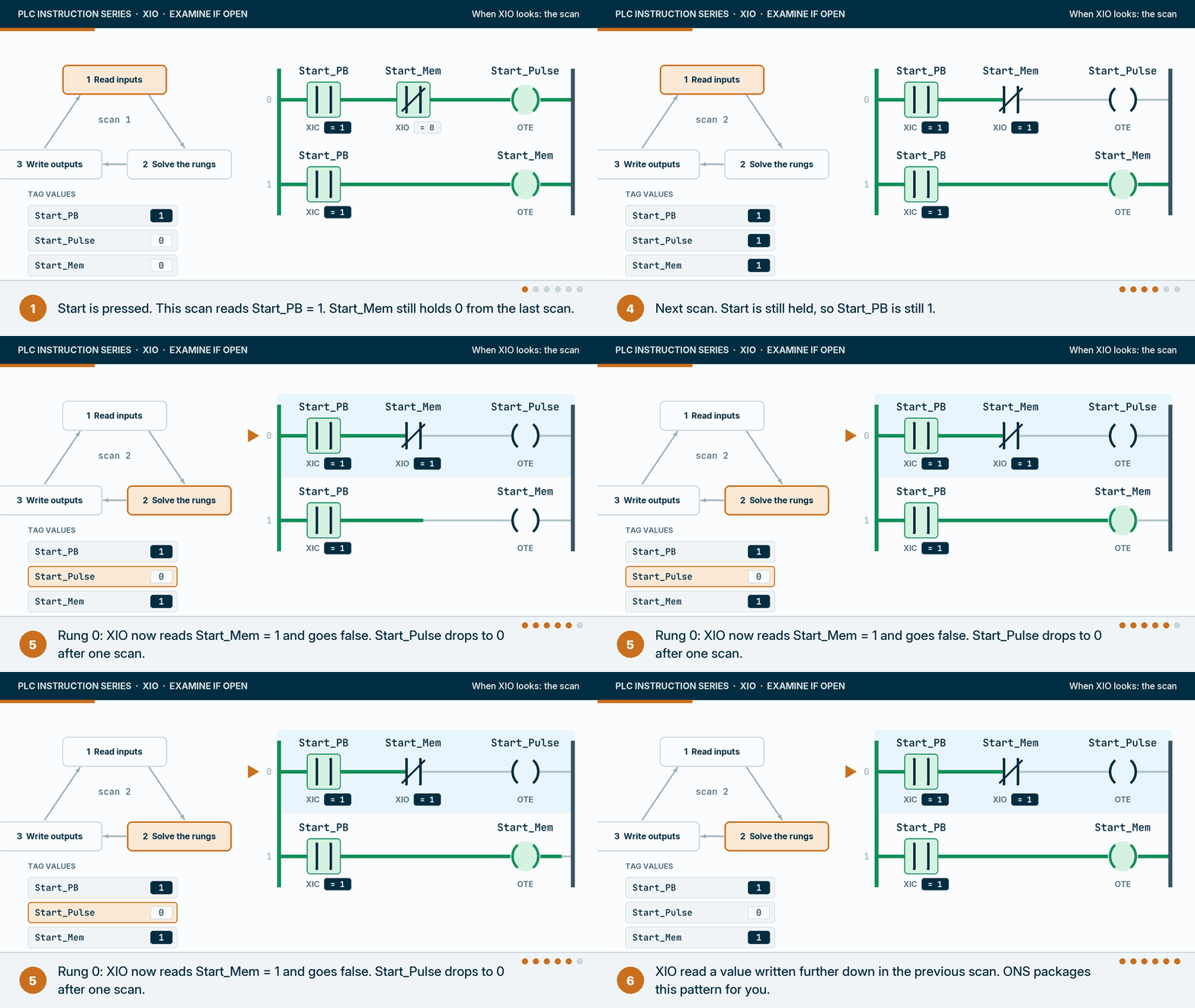
The pattern in the animation is a one-scan pulse built by hand. Rung 0 reads Start_Mem, rung 1 writes it. On the scan where Start is first seen, Start_Mem is still 0 from the scan before, so the XIO passes and Start_Pulse is 1. Rung 1 then sets Start_Mem. On the next scan the XIO sees the 1 and the pulse ends. The one-shot instructions (ONS, OSR and OSF) package this behaviour so you do not have to build it; they get their own page in this guide. Seeing it built from an XIO is the best way to understand what they do.
Prescan, default values and asynchronous inputs
Three more timing facts matter for XIO in particular:
- Prescan passes false. Rockwell’s execution table says XIO passes false during prescan, regardless of its bit. The coils on those rungs are handled the way prescan handles them: OTE bits are cleared, and OTL and OTU leave their bits alone (see the OTE and OTL pages).
- New tags read 0. A tag created in a download, or one nobody has written yet, is 0, so every XIO on it is true from the first scan. If an XIO permissive depends on another machine or a network connection, make sure the bit is written before you trust its 0.
- Logix inputs can change mid-scan. In ControlLogix and CompactLogix controllers, input data arrives asynchronously to logic execution, so two XIOs on the same input in one scan can disagree. Process image controllers, including the Siemens S7-1500 and the SLC 500, read inputs once at the start of the scan. The XIC page shows the buffering fix, which applies unchanged.
XIO in practice: seven scenarios from simple to advanced
Each scenario shows a rung in a particular state, why XIO is the right instruction, and what goes wrong. Tag names are examples, written the way I would want them in a real program.
1. Material handling: forward and reverse interlock
A reversing conveyor has a forward contactor and a reverse contactor, and both must never be energised together. Each direction’s rung carries an XIO on the other direction’s run bit.

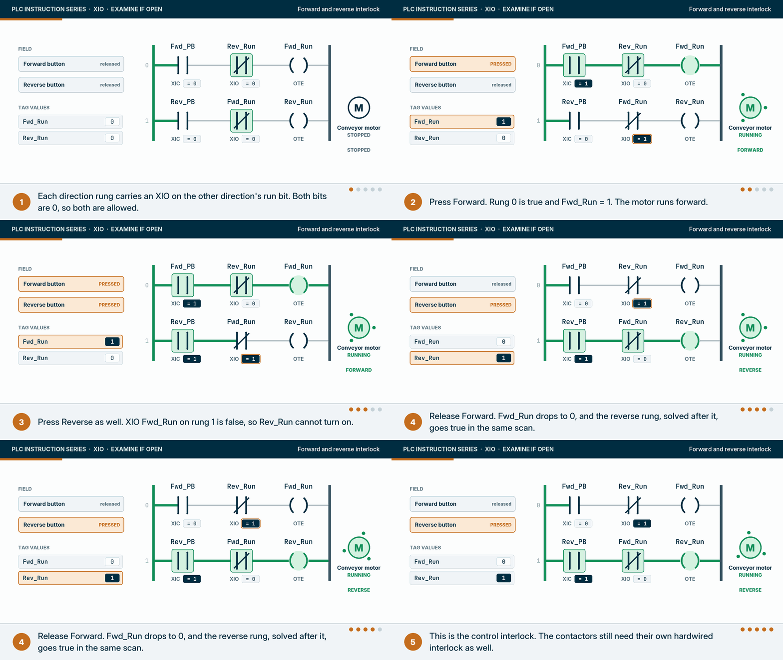
Why XIO: each direction may run only while the other one’s bit is 0. When Forward is released, the reverse rung goes true in the same scan, because it sits below the forward rung and reads the freshly written 0. What goes wrong: that is exactly the problem. Changing direction without a stop lets the second contactor pull in the instant the first one’s bit drops, while the first may still be arcing open. Reversing starters therefore also get a mechanical or hardwired electrical interlock, and many programs add a short off-delay before the other direction is allowed. Many designs also read each contactor’s auxiliary contact, with an XIO on the other contactor’s feedback, so the interlock reflects what the contactor did and not only what the program asked. Treat the XIO as the logic layer, never the only layer.
2. Packaging: feed cartons only while the lane has room
An accumulation lane in front of a case packer has a full sensor near its end. The infeed releases cartons while the lane has room and nothing downstream is jammed.
Why XIO: Lane_Full and Downstream_Jam are both 0 in the state where the infeed should run. What goes wrong: first, gaps: an eye at the end of a lane sees the gaps between cartons, so filter it with an on-delay before trusting it either way. Second, failure: a full-lane photo-eye that fails, or whose cable is cut, reads 0, which the XIO reports as “room in the lane”, and the infeed keeps pushing cartons into a full lane. Where a pile-up would cause damage, choose a sensor mode where failure reads as blocked (a light-operated eye that is on while the beam is clear), and read it with an XIC on a “lane has room” bit instead.
3. Water and wastewater: stop chlorine dosing on low flow
A chlorine dosing pump on a treatment line must not inject into still water. A flow switch reports low flow, and an analyzer reports its own fault.
Why XIO: the pump may run only while Low_Flow and Analyzer_Fault are 0. What goes wrong: the same failure-direction problem in a more serious place. If the flow switch wiring breaks, Low_Flow reads 0 and the pump is allowed to dose into a pipe with no flow. Sound designs take the permissive from a positive “flow proven” signal read with XIC, from a flow transmitter with a range check, and supervise the switch with a discrepancy alarm. On a chemical feed the flow proof is usually also wired into the pump’s own circuit, so a controller fault cannot start the pump on a dry pipe. The XIO version is common in older programs and worth looking for in an audit.
4. Chemicals and process: a low level switch raises an alarm and protects the pump
A supply tank feeds a pump. A low level switch, LSL-201, is wired so that it is closed while wet. When the level falls below it, its bit drops to 0: an XIO on it raises the alarm, and an XIC on the same bit removes the pump’s permit.

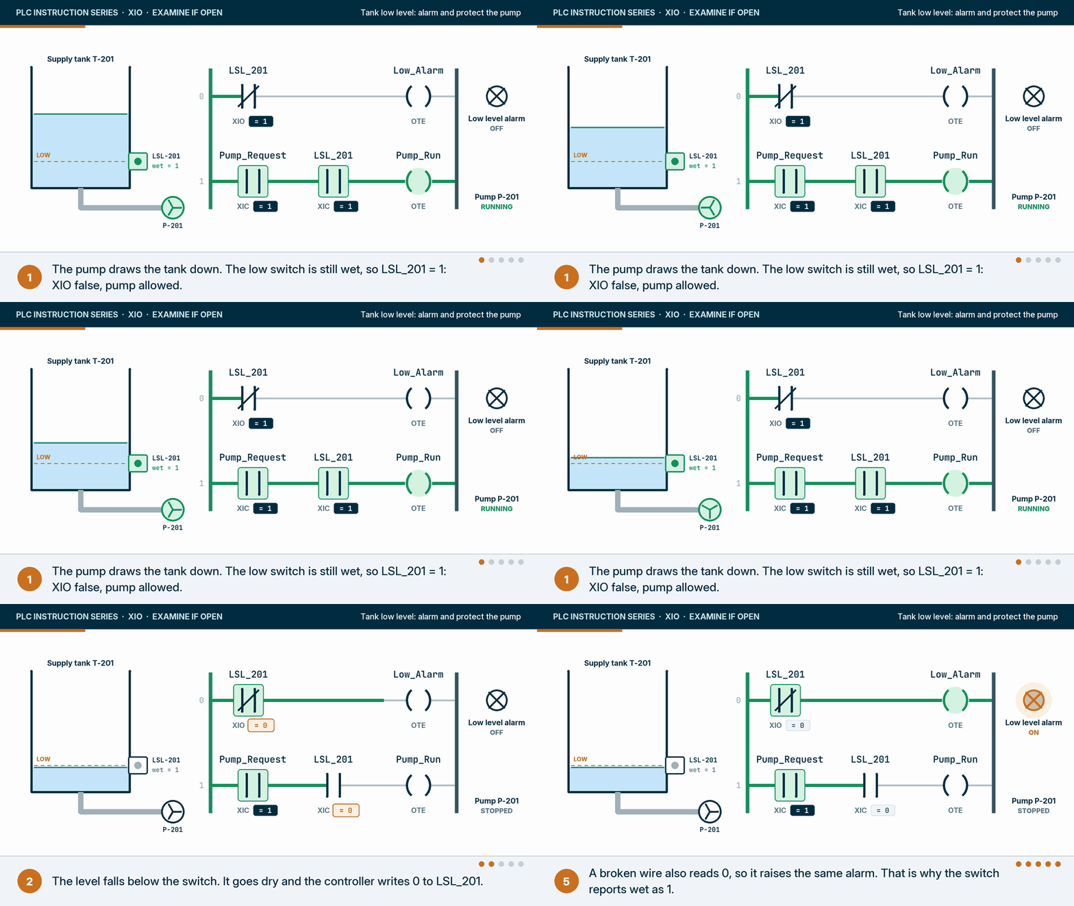
Why XIO: the alarm should be on exactly when the switch reports dry, which is when its bit is 0. This is XIO at its best: because the switch reports wet as 1, a broken wire also reads 0, raises the same alarm and stops the pump. The failure direction is the safe one. What goes wrong: two things. A wave at the switch can chatter the pump, so add a short off-delay or a separate low-low switch for the pump trip. And wiring the switch the other way (closed when dry) while keeping the same logic means a broken wire reads as “wet”, the alarm stays silent and the pump runs dry. Read the loop drawing before you pick the instruction.
5. Food and beverage: a product valve that stays shut during cleaning
A filler’s product valve must never open while the line is in clean-in-place, or caustic and product can meet. The valve rung carries an XIO on CIP_Active and another on the divert valve’s open proof.
Why XIO: the product valve may open only while cleaning is not active and the divert path is not open. What goes wrong: CIP_Active usually comes from another controller or a CIP skid over the network. If that connection drops and the tag freezes at 0, or a new program download resets it to 0, the XIO passes. Interlocks between product and cleaning chemicals are normally backed by physical separation (a swing panel, a mix-proof valve with proven positions or block-and-bleed), and the network bit is supervised with a heartbeat, as in the OEM status word problem on the XIC page.
6. Pharmaceutical: an autoclave door releases only when depressurised
A steam steriliser’s door lock may only release once the cycle has ended and the chamber is vented.
Why XIO: the door may be released only while Chamber_Pressurized and Cycle_Running are 0. What goes wrong, and this one matters: a pressure vessel door interlock is a safety function. It belongs to a safety-rated design with its own pressure sensing and locking, validated to the pressure vessel and steriliser standards that apply and to the performance level its risk assessment requires (ISO 13849-1 is one framework for the control system). Doors on pressure vessels also carry a mechanical lock that cannot be opened under pressure. The standard PLC reads the interlock’s status, sequences the cycle and tells the operator why the door will not open. If a single XIO on a standard input is the only thing between an operator and a pressurised door, the design is wrong, not the rung.
7. Automotive: index the conveyor only when the robot is clear
In a welding cell, the conveyor may index the next body only while the robot is out of the conveyor zone and its communication is healthy.
Why XIO: Robot_In_Zone is 0 when the robot is clear. What goes wrong: that bit arrives over a network from the robot controller. If the connection drops, the bit can keep its last value or reset to 0, depending on how the data arrives, and a 0 reads as “clear”. That is why the rung also carries an XIC on Robot_Comms_OK, built from a heartbeat. This is a sequencing interlock only. Keeping people and the robot apart is the job of the cell’s safety system (ISO 10218 for robots), never this rung.
What does XIO look like in each vendor’s software?
Every ladder editor has the instruction. Rockwell Automation calls it XIO in Studio 5000 Logix Designer and RSLogix 500 (more on those platforms on our Rockwell Automation page). Siemens, Mitsubishi Electric, AutomationDirect and Phoenix Contact call it a normally closed contact. CODESYS and Beckhoff call it a negated contact. The symbol, two bars with a slash, is the same almost everywhere.
| Vendor | Software | Name of the instruction | Example operand | Text form |
|---|---|---|---|---|
| Rockwell Automation | Studio 5000 Logix Designer | XIO, Examine If Open | Jam_Fault, Local:1:I.Data.10 | Rung text XIO(Jam_Fault); ST IF NOT Jam_Fault THEN |
| Rockwell Automation | RSLogix 500 (SLC 500) | XIO, Examine If Open | I:1/10, B3:0/5 | XIO I:1/10 |
| Siemens | TIA Portal (S7-1200, S7-1500) | Normally closed contact | "Jam_Fault", %I0.5 | STL AN "Jam_Fault" on S7-1500 |
| Mitsubishi Electric | GX Works3 (MELSEC iQ-R) | Normally closed contact | X10, M5 | LDI starts a rung, ANI in series, ORI in parallel |
| Phoenix Contact | PLCnext Engineer | Normally closed contact | A named BOOL variable | ST IF NOT Jam_Fault THEN |
| IEC 61131-3 / CODESYS, Beckhoff | CODESYS, TwinCAT 3 | Negated contact | A named BOOL variable | ST IF NOT bJamFault THEN |
| AutomationDirect | CLICK Programming Software | Normally closed contact | X010, C5 | None; ladder only |
Sources: Rockwell Automation 1756-RM003 and 1747-RM001; Siemens TIA Portal V20 help (LAD and STL for S7-1500); Mitsubishi Electric SH(NA)-081265ENG; CODESYS and Beckhoff online help; Phoenix Contact PLCnext Engineer help; AutomationDirect CLICK instruction list.
The same XIO in each vendor’s editor
These are real screenshots of the instruction in 23 programming environments, ordered the same way as on the XIC page: first the platforms that dominate North American plants, then the machine-builder platforms you meet on imported equipment, then compact and regional controllers. Each one is framed the same way, with the instruction ringed in amber and the source credited under it. Pick a tab to switch software. Watch the operand change, from a tag with an alias to a file address to a device number, while the slashed contact stays put. One caution about the first two tabs: those tutorials use a normally open stop button read with an XIO, the pattern this page recommends against for stops.
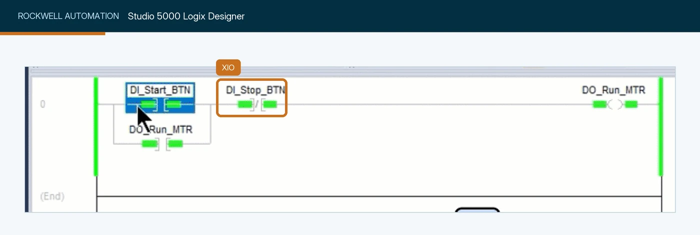
DI_Stop_BTN, in series after the XIC start contact and its DO_Run_MTR seal-in branch, driving the DO_Run_MTR output coil. The XIO is green because the stop button bit is false. Screenshot: RealPars, PLC Latching vs Sealing Explained Simply.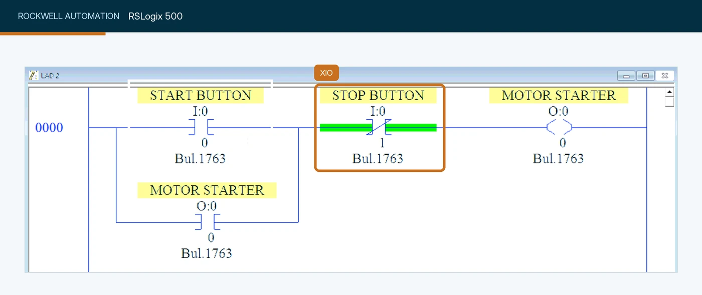
I:0/1, entered as an XIO (green while the button is not pressed) in series with the start branch, driving the O:0/0 motor starter output. RSLogix 500 addresses are file:element/bit. Screenshot: SolisPLC, PLC Programming Fundamentals: XIO Examine If Open Instruction.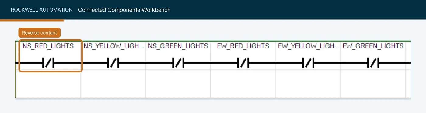
NS_RED_LIGHTS to EW_GREEN_LIGHTS, true only when every one of those variables is false, setting two lights. The first reverse contact is ringed. Screenshot: Rockwell Automation, Micro800 and Connected Components Workbench Getting Started Guide.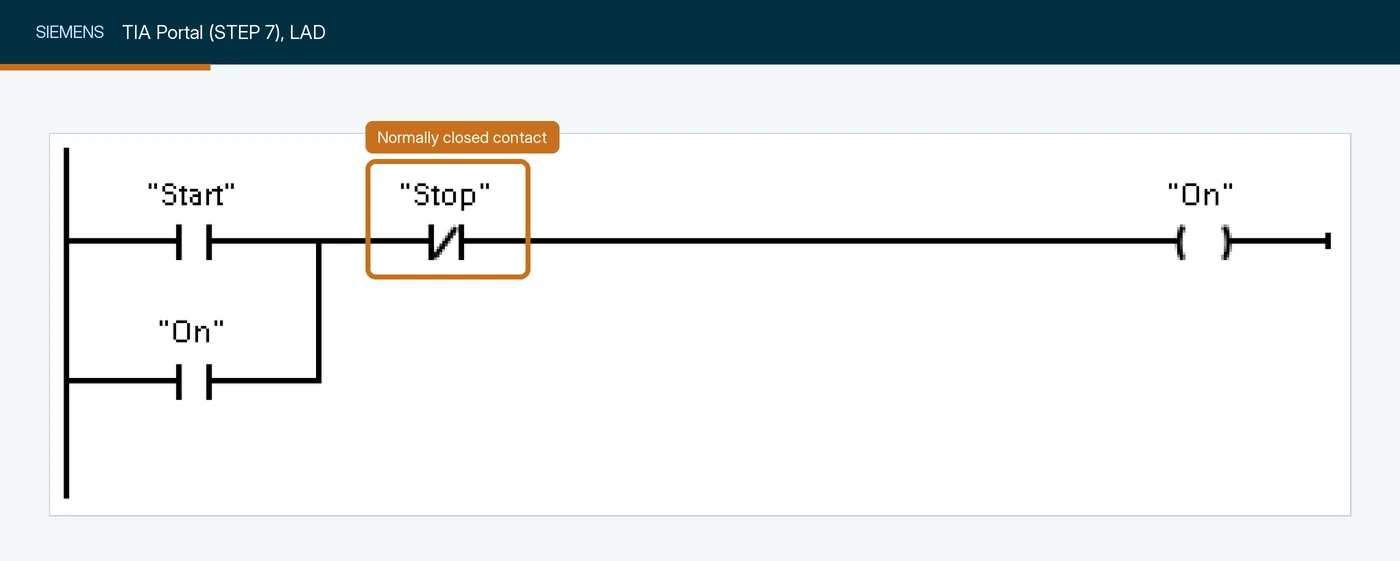
"Stop" in series after the "Start" contact and its "On" seal-in branch, driving the "On" coil. The NC contact passes power only while "Stop" is false. Screenshot: Siemens AG, S7-1200 Easy Book.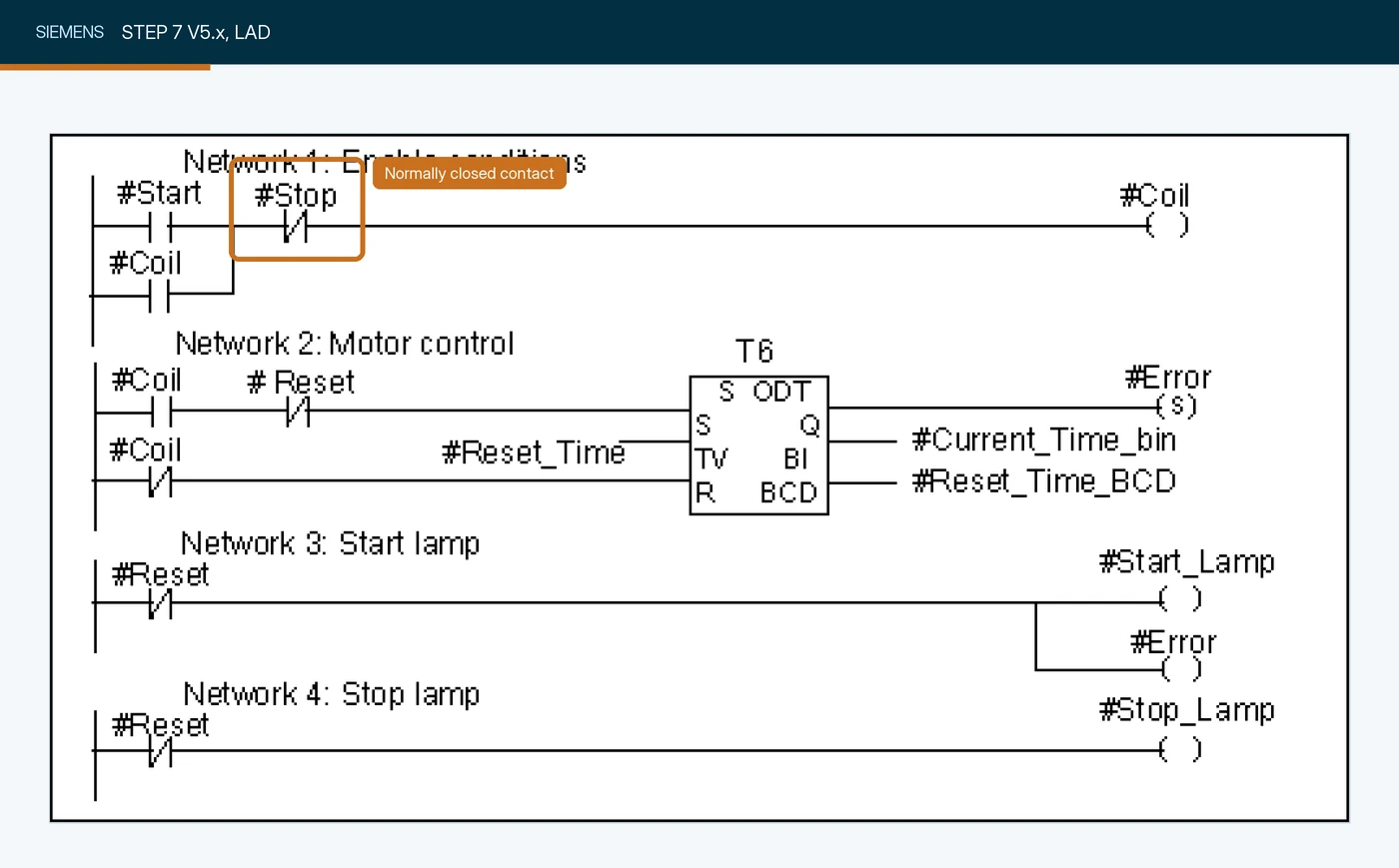
#Stop in series with the #Start contact, driving the #Coil output in Network 1. STEP 7 Classic draws the NC contact with a slash. Screenshot: Siemens AG, Programming with STEP 7.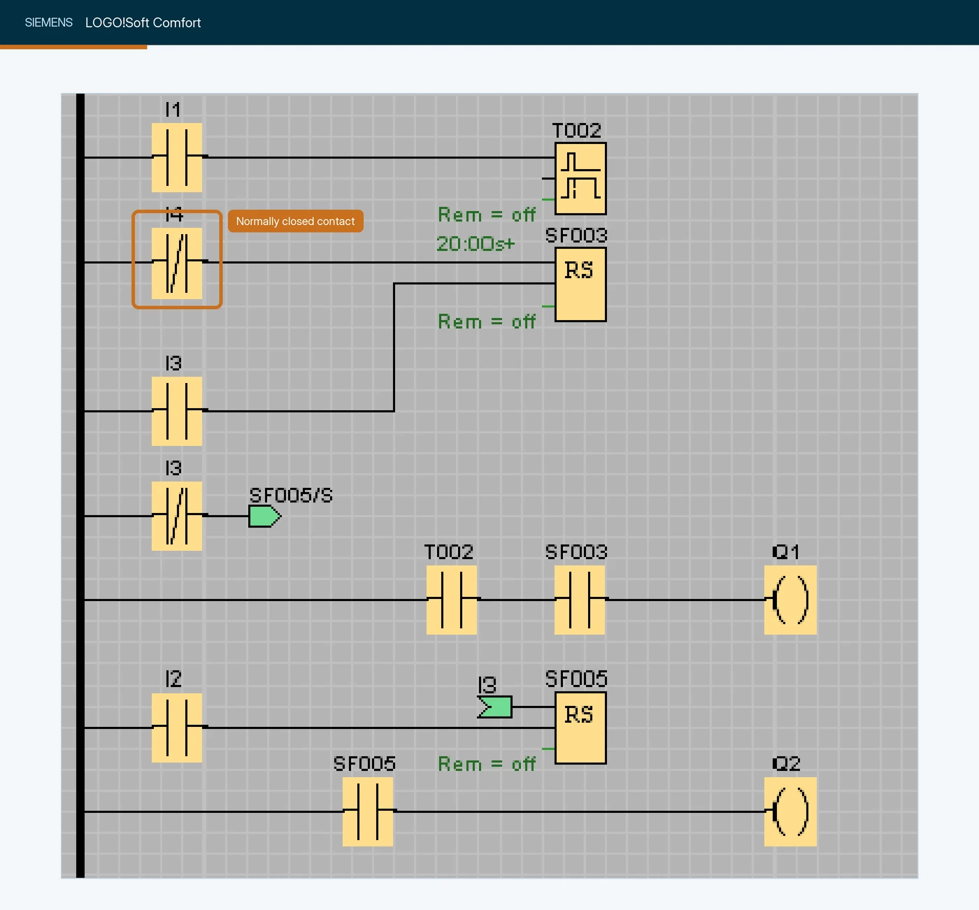
I4 (drawn with a slash) beside normally open contacts on I1, I3 and I2, in a network that drives relay coils Q1 and Q2. LOGO! operands are I, Q and M addresses. Screenshot: Siemens AG, LOGO!Soft Comfort V8.4 Online Help.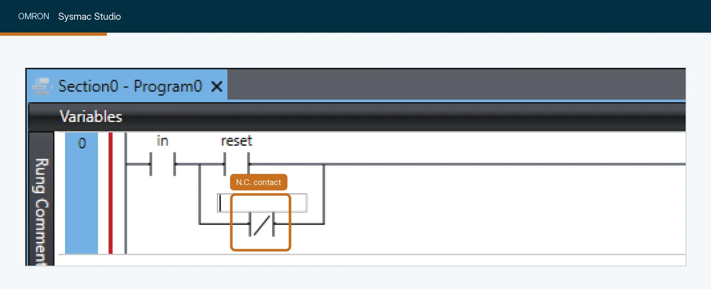
in and reset contacts, next to coil out. Its variable box is still empty. Screenshot: Omron, Sysmac Studio Version 1 Operation Manual (W504).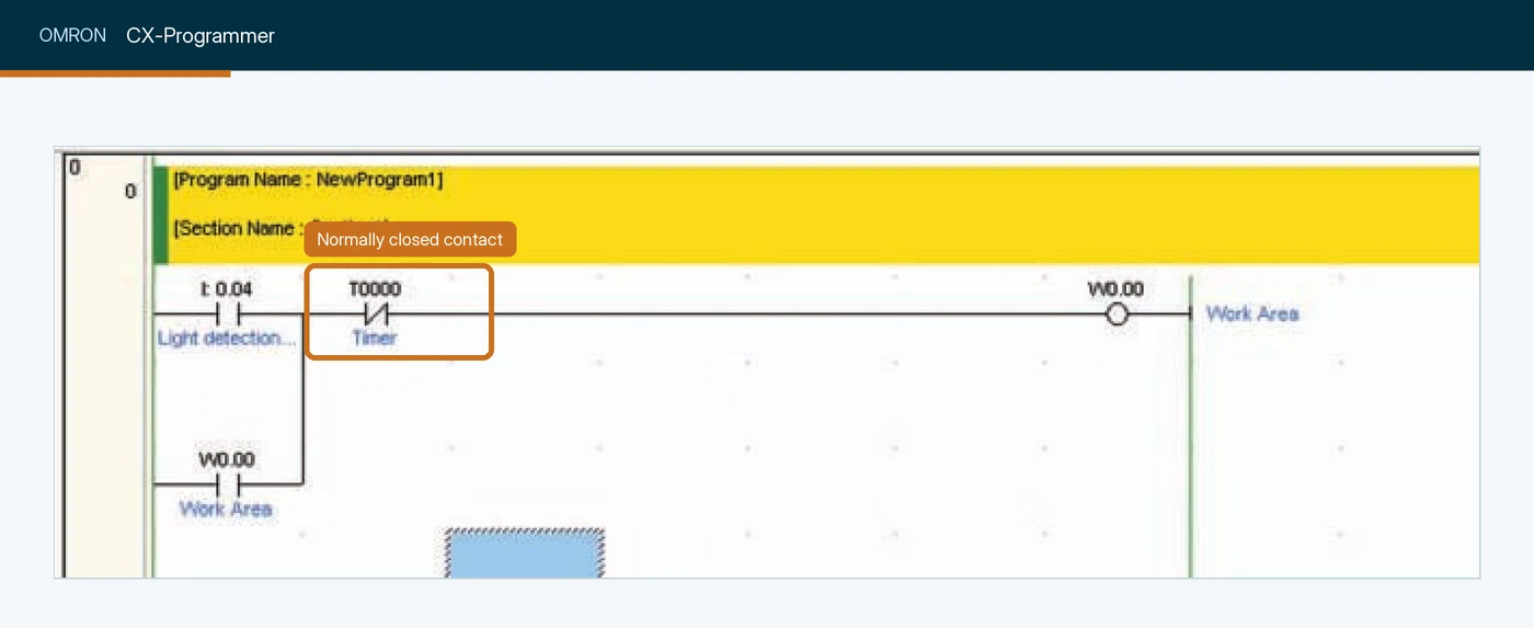
T0000 in series after the normally open I 0.04, driving output W0.00 with a W0.00 seal-in below. Omron operands are memory addresses (I, W, T). Screenshot: Omron, CP1L/CP1E CPU Unit Introduction Manual (W461).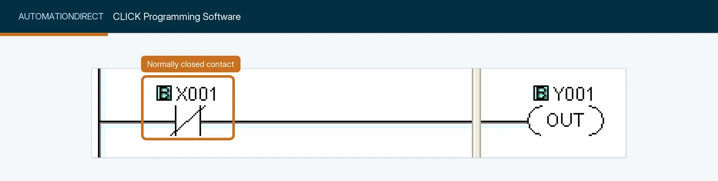
X001 driving output Y001, so the coil is on while the input is off. Screenshot: AutomationDirect, CLICK help, Normally Closed Contact.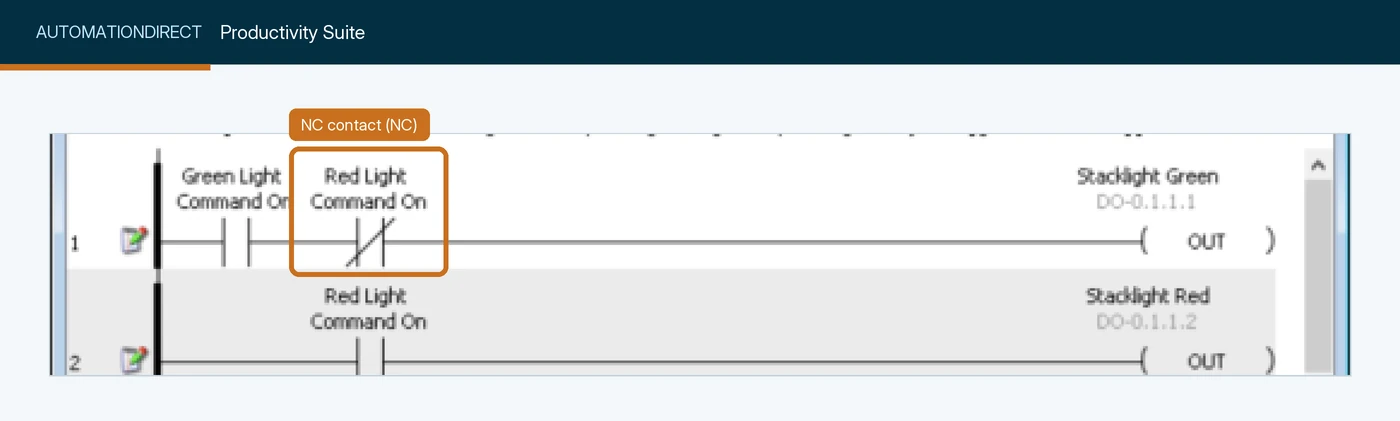
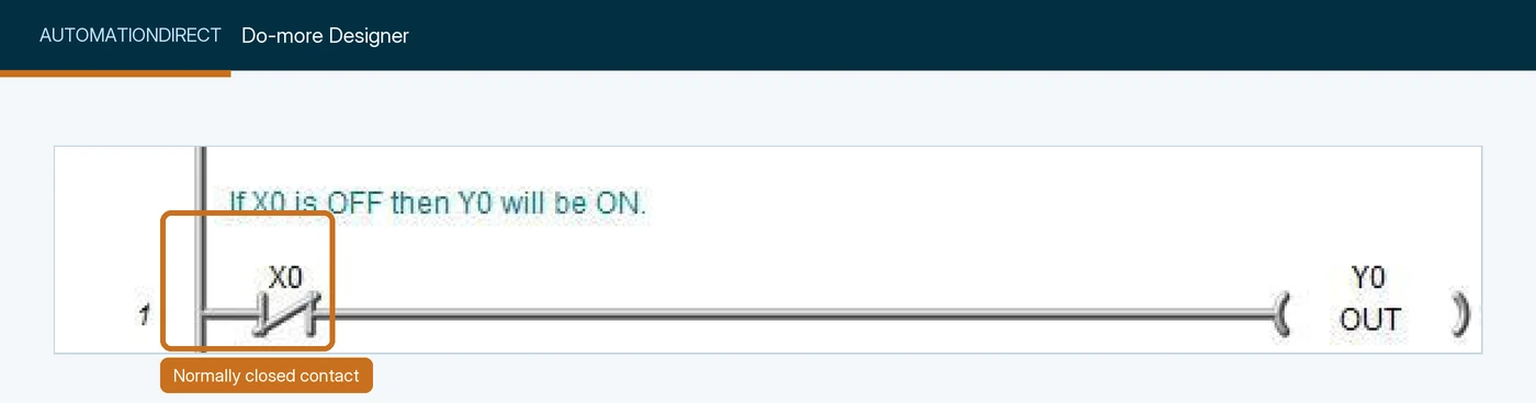
X0 driving output Y0, under a plain-language rung comment. Screenshot: AutomationDirect, Do-more Designer help, (CONTACT) - Normally Closed.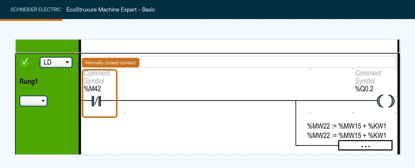
%M42 driving output %Q0.2. Screenshot: Schneider Electric, EcoStruxure Machine Expert - Basic, Operating Guide (EIO0000003281).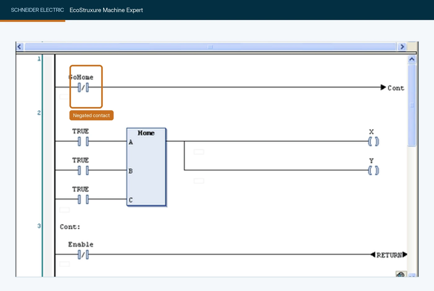
GoHome, ahead of a jump to the Cont label. Screenshot: Schneider Electric, Machine Expert help, Working in the FBD and LD Editor.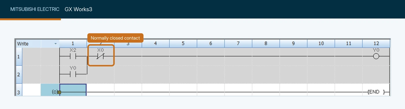
X0 in series with a start contact, feeding output Y0. Screenshot: Mitsubishi Electric, FX5U Training Manual.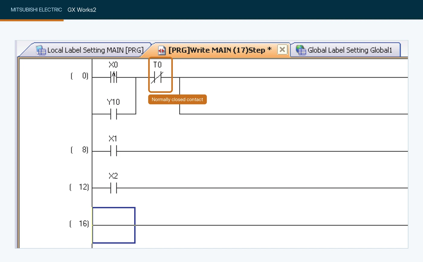
T0 in the first rung of a simple project. Screenshot: Mitsubishi Electric, GX Works2 Beginner's Manual (Simple Project).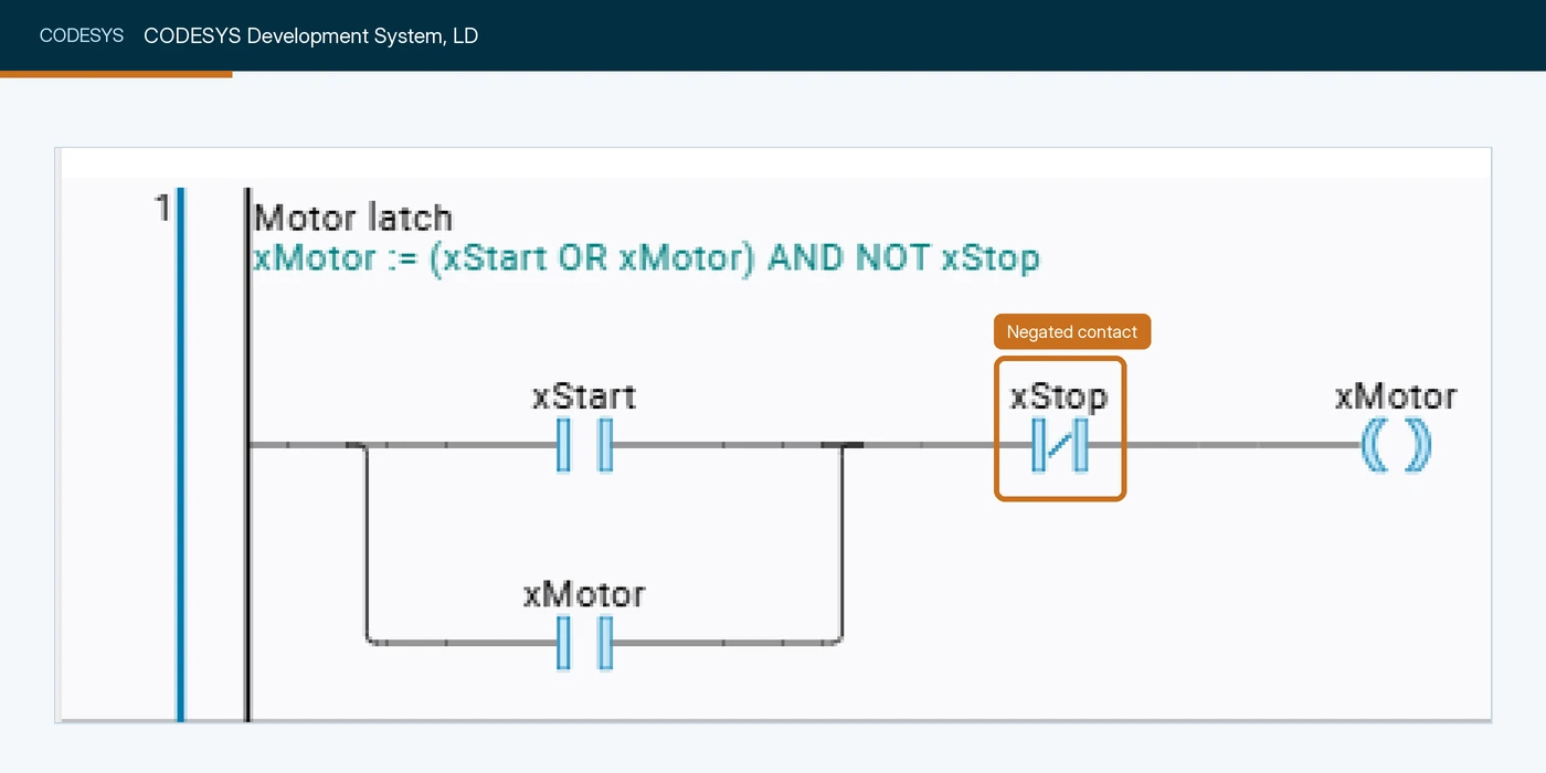
xStop in a motor start/stop rung, so the motor drops out when the stop is pressed. Screenshot: CODESYS Group, CODESYS 4 online help, Binary circuits.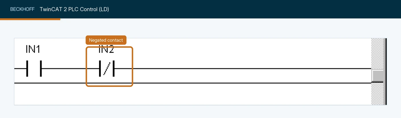
IN2, which conducts only while its variable is FALSE. Screenshot: Beckhoff Automation, Ladder Diagram Editor (TwinCAT PLC Control).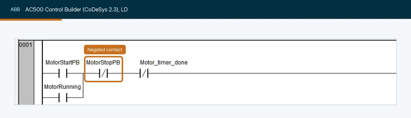
MotorStopPB, in series with the start contact and its MotorRunning seal-in branch. Screenshot: ABB, My first project with AC500 eCo PLC (LVD-EOTN112U-EN).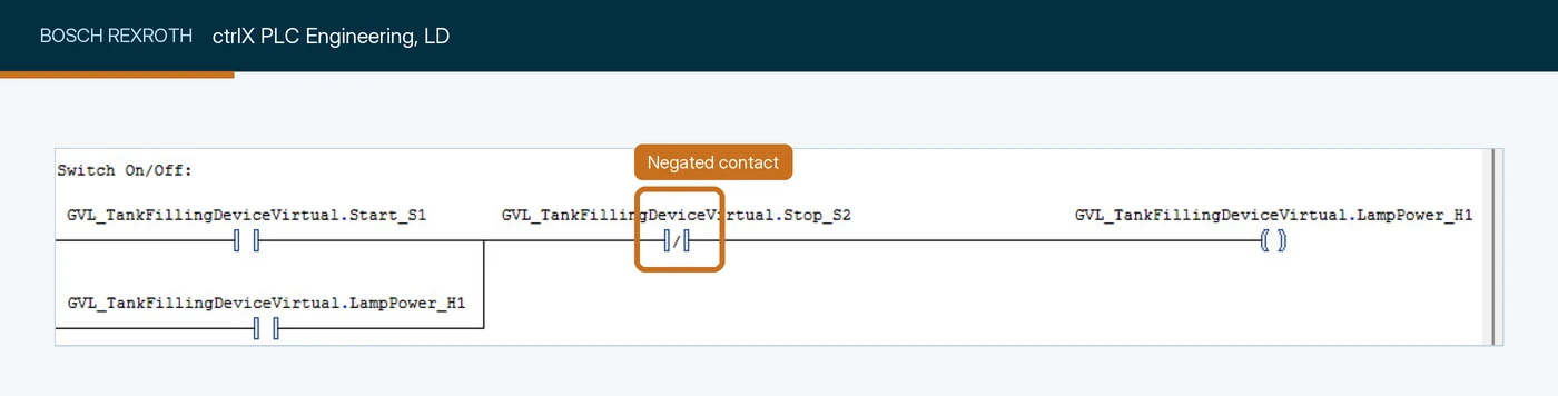
Stop_S2, in series with the start contact that drives the LampPower_H1 coil. Screenshot: Bosch Rexroth community, How to run a ladder diagram simulation using ctrlX PLC 1.20.7 (forum post).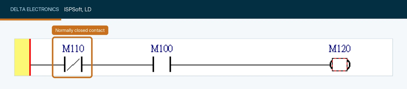
M110, in series with a normally open contact and an output coil. Screenshot: Delta Electronics, ISPSoft User Manual.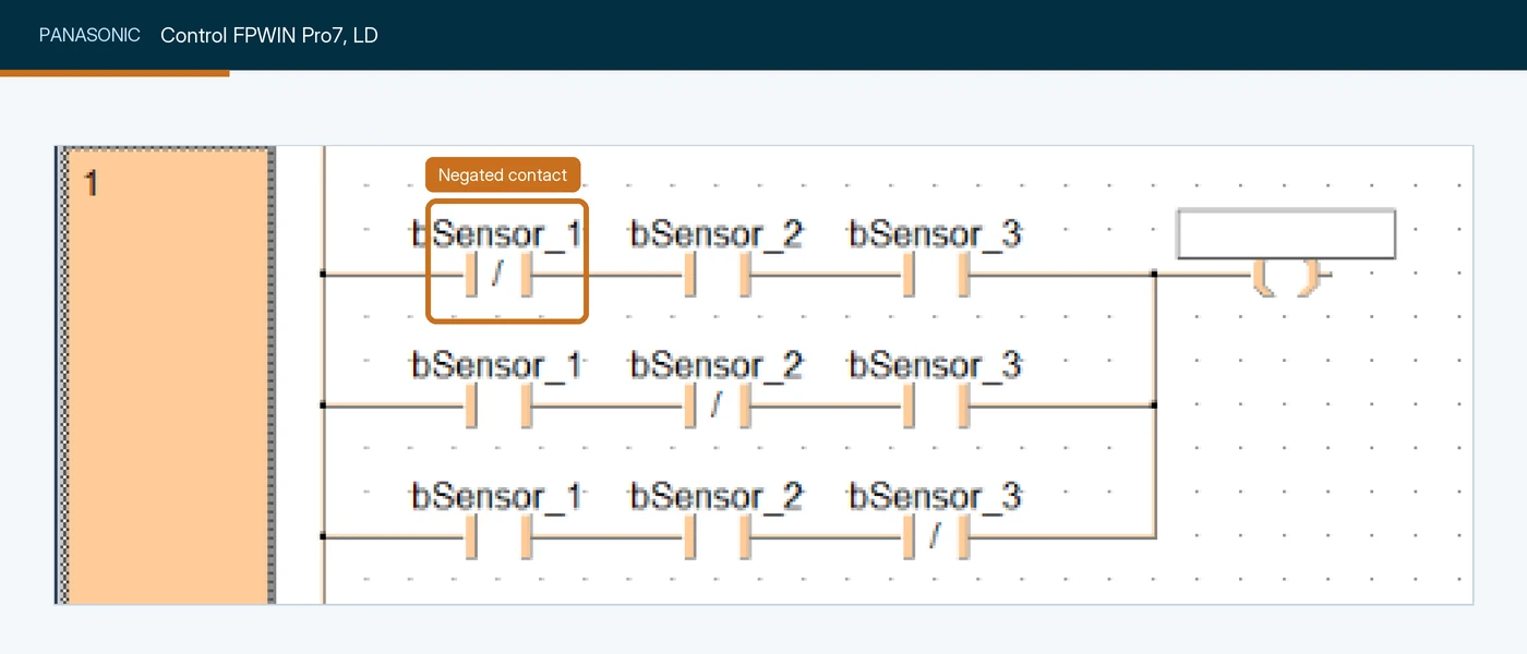
bSensor_1, one of three contacts, each negated in turn in a parallel branch. Screenshot: Panasonic Industry, Control FPWIN Pro7 help: Assign contacts and coil.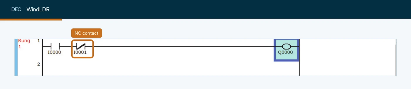
I0001, in series with a NO contact and the output coil Q0000. Screenshot: IDEC Corporation, FC6A Series MicroSmart LAD Programming Manual (FC9Y-B1726).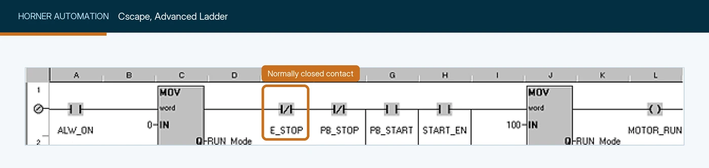
E_STOP, one of two in series after a function block and before the coil. Screenshot: Horner Automation Group, Cscape help: Contacts and Coils in Advanced Ladder.| Vendor | Software | Why it is not shown yet |
|---|---|---|
| Schneider Electric | EcoStruxure Control Expert (Modicon M340, M580) | The manual’s LD chapter shows only drawn symbols, with no editor window. Machine Expert and Machine Expert - Basic are shown above. |
| Emerson | PAC Machine Edition | No public screenshot of a normally closed contact in the editor. |
| Phoenix Contact | PLCnext Engineer | No public screenshot of a normally closed contact in the editor; the help page that has one was blocked to automated fetch. |
| KEYENCE | KV STUDIO | The manuals sit behind a download form and no public screenshot of the ladder editor turned up. |
| B&R | Automation Studio | No public screenshot of the LD editor. |
| Inovance | InoProShop, AutoShop | The public manuals have no ladder editor figures. |
| WAGO | e!COCKPIT | No public LD screenshot; it is built on CODESYS, shown above. |
If you work in one of these, the instruction is the same normally closed contact; we will add your editor when we capture it ourselves.
Two differences matter when you switch platforms. Siemens builds logic on the result of logic operation (RLO): on an S7-1500, STL AN checks an operand for 0 and ANDs it with the RLO, which is a series XIO. And Mitsubishi Electric’s instruction list makes the structure explicit with LDI to start a rung on a normally closed contact and ANI or ORI to add one in series or in parallel. If you want a practice environment, I have walked through installing RSLogix 500 for free and TIA Portal.
Why is my XIO true when it shouldn’t be? A debugging checklist
An XIO that is true at the wrong moment almost always means its bit is 0 for a reason you did not expect. Work from the rung back to the field.
- Check the rung to its left. XIO can only pass true if the rung condition reaching it is true.
- Read the bit in a tag monitor. Confirm the value and the scope. A program-scoped tag with the same name as a controller-scoped one shadows it, and the program tag may never be written.
- Find every writer. Cross-reference the tag. No writer at all means the bit is stuck at its initial 0 and the XIO is permanently true. More than one writer means the last one to execute wins.
- Check the input card’s indicator. If the device is on but the input’s light is off, the problem is in the field: the device, the wiring, the fuse or the supply. A dead circuit reads 0 and makes every XIO on it true.
- Check the module and its connection. A faulted module or a lost connection can leave input data at a stale or cleared value. Check the module’s status before trusting the tag.
- Check network bits at their source. For bits from another controller, a robot or a skid, confirm the connection is healthy and the other side is actually writing.
- Look for a force. A forced bit holds 0 or 1 whatever the field does.
- Think about timing. In Logix, an input that changes mid-scan can be 0 for one XIO and 1 for another in the same scan.
Step 3 deserves the emphasis. “Nothing writes this tag” is a problem only XIO can hide: an XIC on an orphaned tag is dead and someone notices; an XIO on it is quietly true for years. Version control for PLC code and a cross-reference review at every change are how plants catch it.
Common XIO mistakes
| Mistake | What happens | Fix |
|---|---|---|
| XIO on a normally closed stop button | The machine has no permit at rest and gets one while Stop is pressed | Choose from the bit’s value when the rung should pass: XIC |
| XIO permissive on a signal that reads 0 when it fails | A broken wire or lost connection grants the permit | Use a fail-safe signal read with XIC, or supervise the signal |
| XIO on a tag nothing writes | The rung is permanently true | Cross-reference every XIO tag; delete or wire up orphans |
| Long chains of XIOs on separate fault bits | Hard to troubleshoot online; one is easily missed | Build one summary fault bit and read it once |
| Program interlock with no hardware interlock | Two contactors can pull in during a direction change | Add a mechanical or hardwired interlock and an off-delay |
| XIO used as the safety function | Safety depends on standard logic | Safety relay or safety controller; the PLC reads status only |
Test yourself: an interview quiz on XIO
Ten questions, the kind I'd ask in an interview for a controls role to see whether someone really understands XIO. Pick an answer and the explanation appears straight away.
0 of 10 answered
In one sentence, what does an XIO instruction test?
XIO reads a bit in memory and is true when that bit is 0. It never looks at the switch or the terminal directly.
A stop button is wired normally closed. Which instruction belongs in the rung that lets the machine run?
At rest the normally closed contact conducts, so the bit is 1. The rung should pass in that state, which is what XIC does. An XIO would be false at rest and true while Stop is pressed.
In a Logix controller, what does an XIO pass to the right during prescan?
Rockwell's execution table for XIO sets the rung condition out to false during prescan and postscan.
The wire to a fault contact breaks. The fault bit drops to 0. What does an XIO on that bit do?
XIO is true whenever the bit is 0, whatever the reason. That is why an XIO permissive on a signal that reads 0 when it fails needs supervision or a fail-safe redesign.
Two XIOs are in series on bits A and B. When is the rung true?
Series is AND: NOT A AND NOT B. Any bit at 1 breaks the chain, which is why a series of XIOs on fault bits means 'no faults at all'.
Rung 0 has an XIO on Run_Mem. Rung 5 writes Run_Mem. What does the XIO on rung 0 see?
Rung 0 executes before rung 5 in the scan, so it reads the value left by the previous scan. That timing is how a hand-built one-scan pulse works.
What is the structured text equivalent of XIO(Jam_Fault)?
There is no XIO in structured text; you test the bit with NOT inside an IF.
Which name does CODESYS use for the XIO symbol?
CODESYS and Beckhoff TwinCAT call it a negated contact. Siemens, Mitsubishi Electric and AutomationDirect call it a normally closed contact.
An XIO on a tag is true all the time and the cross reference shows no writer. What is the most likely cause?
A tag nothing writes keeps its initial value, normally 0, so an XIO on it is permanently true. Misspelled or shadowed tags cause exactly this.
Why should a forward/reverse program interlock built with XIOs not be the only interlock?
The program interlock is a logic layer. Reversing starters also get a mechanical or hardwired interlock, and often an off-delay, so both contactors can never be closed together.
That's the basics covered. If you'd like the next instruction in this guide in your inbox, the sign-up is below. It's never needed to see an answer.
Five harder XIO problems
These are commissioning-grade problems. Try each on paper before opening the solution. The rungs are written in Logix rung text: XIC(tag) and XIO(tag) are contacts, square brackets with commas are parallel branches, and OTE(tag) is the output coil.
Problem 1: the infeed that never stops on a dead sensor
A case packer infeed uses XIC(Infeed_Running) XIO(Lane_Full) OTE(Infeed_Release). The lane-full photo-eye is a dark-operated sensor: its output is on while the beam is blocked. Twice this month a cable was crushed by a forklift and the infeed buried the packer in cartons. Redesign the signal and the rung so a dead sensor stops the infeed.
Show the solution
Switch the sensor to light-operated, so its output is on while the beam is clear, and name the bit for what a 1 means: Lane_Has_Room. Then read it with XIC:
XIC(Infeed_Running) XIC(Lane_Has_Room) OTE(Infeed_Release);Now every failure that makes the input read 0 (a crushed cable, a dead sensor, a lost supply) reads as “no room” and stops the infeed. The original rung failed the other way because the XIO treated 0 as good news. A sensor whose output has failed on, or one aimed at the wrong reflector, can still read 1, so for a lane where a pile-up causes real damage, add a supervision rung: if Lane_Has_Room has not changed state for longer than the lane could plausibly run without a gap, raise a sensor alarm. That timer belongs to the timers page in this guide.
Problem 2: a one-scan pulse that never fires
A colleague built a manual one-shot for a reject counter:
XIC(Reject_PE) XIO(Reject_Mem) OTE(Reject_Pulse);
XIC(Reject_PE) OTE(Reject_Mem);
XIC(Reject_Pulse) ADD(Reject_Count, 1, Reject_Count);
It counts correctly in testing. In production, after someone moved the second rung to the top of the routine to “keep the memory bits together”, the count stays at zero. Explain why, and say how to make the pattern reliable.
Show the solution
The pattern depends on scan order. The XIO must read Reject_Mem before it is written in the same scan, so it sees last scan’s value. With the memory rung moved above it, Reject_Mem is set to 1 earlier in the same scan, the XIO reads 1 and is false, and Reject_Pulse is never true. Nothing counts.
The reliable fix is to use the instruction built for the job, which keeps the storage bit inside the instruction so rung order cannot break it:
XIC(Reject_PE) ONS(Reject_ONS) ADD(Reject_Count, 1, Reject_Count);If you keep a hand-built version for a reason, put the read and the write on the same rung, in that order, and comment it. On Logix, also buffer the input once at the top of the routine: an input can change between the two rungs, set the memory bit and never fire the pulse. ONS avoids that by reading the rung once. The lesson for XIO is general: an XIO on a bit written later in the scan reads the previous scan’s value, and moving rungs changes the answer.
Problem 3: the CIP interlock after a download
The filler’s product valve rung is XIC(Fill_Step) XIO(CIP_Active) OTE(Product_Valve_Open). CIP_Active is a consumed tag from the CIP skid’s controller. During a weekend download of the filler program, the connection to the skid is down for several minutes while the skid is in its caustic step. What value does CIP_Active have, what can happen, and how should the rung be built?
Show the solution
You cannot know for certain without testing the connection’s fault behaviour, and that is the problem. Depending on how the data arrives, a consumed tag may hold its last value or may not be updated at all after a download, and a freshly downloaded tag starts at 0. If it reads 0, the XIO passes, and a fill step could open the product valve while caustic is in the line.
Build the permissive from positive proof that the skid is not cleaning and that you are still hearing from it:
XIC(CIP_Idle) XIC(CIP_Link_OK) XIO(CIP_Active) OTE(CIP_Permit);
XIC(Fill_Step) XIC(CIP_Permit) OTE(Product_Valve_Open);
CIP_Idle is a bit the skid sets to 1 only when it is idle, CIP_Link_OK comes from a heartbeat check and the connection’s own status, and the XIO stays as a second check. With this design, every communication failure removes the permit. And because product and caustic meeting is a serious hazard, the physical separation (mix-proof valves with proven positions, or a swing panel) stays the real protection.
Problem 4: interlock two conveyors that share a transfer
Two infeed conveyors, A and B, feed one transfer plate. Only one may run onto the plate at a time, A has priority, and a conveyor that loses its turn must wait until the other is stopped and its photo-eye Plate_Clear reports the plate empty. Write the two run rungs, each with its own request bit.
Show the solution
XIC(A_Request) XIC(Plate_Clear) XIO(B_Run) OTE(A_Run);
XIC(B_Request) XIC(Plate_Clear) XIO(A_Run) [XIO(A_Request) ,XIC(B_Run) ] OTE(B_Run);
Each run rung needs the other conveyor stopped (an XIO on its run bit) and the plate clear. The priority comes from the branch in B’s rung: while A is asking, B cannot start, but the XIC(B_Run) path lets a B that is already running carry on, so A wins contention without interrupting a transfer in progress. Rung order breaks the tie inside one scan, because A’s rung runs first and B’s XIO on A_Run sees A’s new value straight away.
Two practical points. Plate_Clear is read with XIC, so a dead plate sensor stops both conveyors rather than letting both run onto an occupied plate. And both rungs will drop out as soon as a product reaches the plate, so in a real program each run bit is held by a seal-in or a short sequence until the product has fully transferred. Those belong to the OTE and timer pages; the XIO’s job is the mutual exclusion.
Problem 5: the permissive that was always true
A mixer will not stop when its high-torque alarm should stop it. The run rung is XIC(Mixer_Start_Seal) XIO(Mixer_HiTorque) OTE(Mixer_Run). You find:
- The drive’s high-torque output lights its terminal LED during a test.
Local:3:I.Data.7goes to 1 during the test.- The controller-scoped tag
Mixer_HiTorqueis an alias forLocal:3:I.Data.7. - The rung is in the routine
Mixer_Logicof the programMixer, which was copied from another line. - Online, the XIO on
Mixer_HiTorquestays true during the test.
What is wrong, and how do you stop it happening again?
Show the solution
Facts 1 to 3 show the signal reaching the controller-scoped alias correctly. Fact 5 says the XIO never sees it, so the XIO is reading a different tag. In Logix, a program-scoped tag takes precedence over a controller-scoped tag of the same name inside that program (Rockwell’s tag scope documentation describes this). The copied Mixer program most likely brought a program-scoped Mixer_HiTorque with it. Nothing writes that tag, so it is 0, and the XIO on it is permanently true. With an XIC the same mistake would have stopped the mixer and been found on day one; with an XIO it hid until the alarm was needed.
Delete the program-scoped duplicate after checking nothing else in the program uses it, so the rung binds to the controller tag, then test the trip again. To prevent it, review imported programs for program tags that shadow controller tags, run a cross-reference on every XIO tag for “no writer”, and use a naming standard that makes scope obvious.
Keep learning between pages
Sign up for The Plant-Side Brief, Joltek's free weekly email for controls engineers and technicians. Every answer on this page stays open whether you sign up or not.
Where XIO fits in this guide
XIO is the second instruction in Joltek’s PLC Programming guide, after XIC. Between them, they are every input contact you will read in a ladder program. The next page covers the instruction those contacts feed: the output coil, OTE, followed by latch and unlatch, the one-shot, and then timers and counters. The instruction glossary lists them all.
If your team needs this kind of grounding on its own equipment and programs, that is what our hands-on PLC and SCADA training for plant teams is for.
References and further reading
- Logix 5000 Controllers General Instructions Reference Manual (1756-RM003) · Rockwell AutomationExamine If Open (XIO): operand, execution table, prescan and postscan. Read in revision P (December 2014).
- SLC 500 Instruction Set Reference Manual (1747-RM001) · Rockwell AutomationXIO in RSLogix 500, including the normally closed overload example on I:0/10.
- LAD (S7-1200, S7-1500): Normally closed contact · Siemens, TIA Portal V20 online help
- MELSEC iQ-R Programming Manual (Program Design), SH(NA)-081265ENG · Mitsubishi ElectricNormally closed contact and the LDI, ANI and ORI instructions.
- CODESYS LD/FBD: Contact · CODESYS Group, online help
- LD Language Elements · Phoenix Contact, PLCnext Engineer help
- SIMATIC S7-1500 Cycle and Response Times, Function Manual · SiemensThe process image of the inputs is read at the start of each cycle.