
PLC Programming
OTE Instruction (Output Energize): What It Really Writes in a PLC
The OTE instruction writes the rung result into one bit. How it works, why two OTEs on one bit fight, prescan, OTE vs OTL, and 26 vendor editors.
Table of contents
Every rung you have ever read ends in an instruction like this one. The OTE, Output Energize, is the output coil: the place where a ladder rung’s answer gets written down. Most tutorials describe it as “turns the output on when the rung is true”. That sentence is half the story, and the missing half causes some of the most stubborn bugs in plant programs: duplicate coils that fight each other, HMI buttons that do nothing, and outputs that drop out after a mode change. The OTE writes one bit, every time its rung is solved, whatever the rung says. Once you see it that way, those bugs explain themselves.
This page follows the same pattern as the XIC and XIO pages: it starts with one rung and one motor, and works up to scan order, prescan, how the tag becomes a voltage on a terminal, and how every major vendor writes the same coil. At the end there is a quiz and five harder problems with worked solutions.
The short version. OTE writes the rung condition into one bit: 1 when the rung is true, 0 when it is false, every time the rung is solved. It is not a latch. Give every bit exactly one owner: one OTE, and no other instruction, rung or HMI writing the same bit.
What is the OTE instruction?
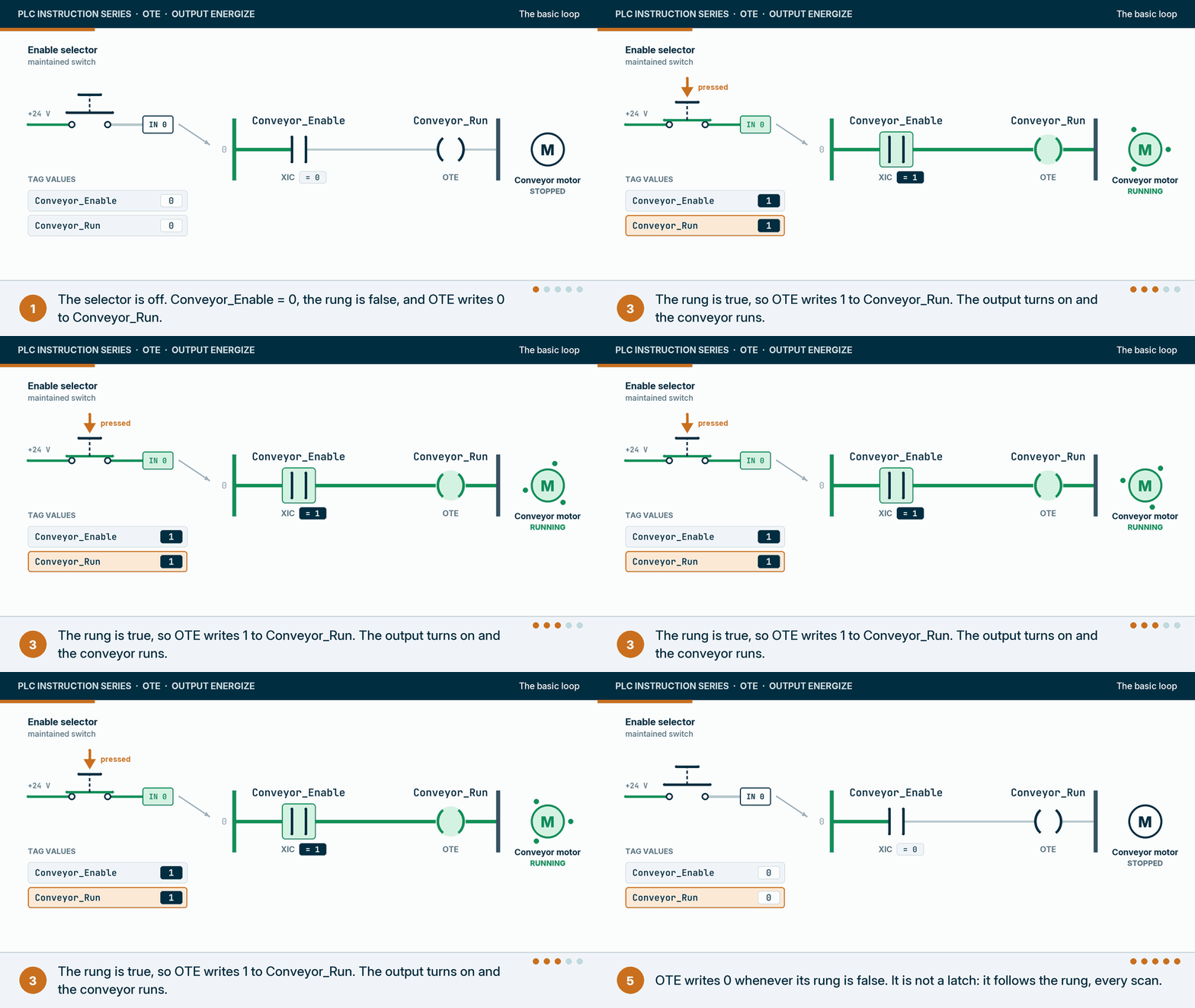
The OTE instruction, short for Output Energize, is a ladder logic output instruction that writes one bit. When the rung condition reaching it is true, OTE sets the bit to 1. When the rung condition is false, it clears the bit to 0. Rockwell Automation calls it OTE; most other vendors call it a coil, and Siemens calls it an assignment.

Rockwell’s Logix 5000 general instructions reference manual (publication 1756-RM003) gives OTE one BOOL operand, the bit to be set or cleared, and this execution table:
| Condition when the OTE executes | What happens to the bit | Rung condition out |
|---|---|---|
| Prescan (when the controller enters Run mode) | Cleared to 0 | False |
| Rung condition coming in is false | Cleared to 0 | False |
| Rung condition coming in is true | Set to 1 | True |
| Postscan | Cleared to 0 | False |
Source: Rockwell Automation, Logix 5000 Controllers General Instructions Reference Manual, 1756-RM003, revision P, OTE section.
Three rows out of four write a 0. That is the most important thing on this page. OTE is not “turn on”; it is “make this bit equal to the rung”. The manual also says OTE does not affect the arithmetic status flags and has no fault conditions. There is no OTE in structured text. The manual’s equivalent is a non-retentive assignment, written Conveyor_Run [:=] Conveyor_Enable;, which is cleared in prescan and postscan the way an OTE is. The ordinary := assignment is retentive.
What does the OTE instruction actually write?
OTE writes a bit in controller memory, not a terminal. For a physical output, that bit is an output tag that the I/O system later copies to the module. For everything else, which is most OTEs in a real program, the bit is internal: a permissive, a sequence step, an alarm, or a request that another rung reads.
The operand can be any BOOL. In Logix that includes an output point such as Local:2:O.Data.0, a tag such as Pump_Run, a member of a user-defined type such as Pump101.Run_Cmd, or one bit of a DINT such as Cmd_Word.5. Rockwell’s SLC 500 manual (1747-RM001) lists the files an OTE may address: outputs, inputs, status, bits, timers, counters, control, integers and more. An OTE on an input address is allowed, and it is almost always a mistake, because the input scan overwrites it.

The SLC 500 manual adds behaviour that every OTE user should know: OTE bits are reset when the controller enters or returns to Run or Test mode, when power is restored, and when the OTE sits in a false master control reset (MCR) zone. It also gives a trap specific to subroutines. A bit set by an OTE in a subroutine stays set until that subroutine is scanned again. Stop calling the subroutine and its OTEs freeze at their last value; they do not drop out. That is documented for the SLC 500; in Logix a routine that is not called is not scanned either, so the same applies.
Why do two OTEs on one bit fight? The last rung wins
Every OTE writes its bit when its rung is solved, true or false. Put two OTEs on the same bit and each one overwrites the other on every scan. The one that executes last decides the value the bit ends the scan with, and rungs in between see the first one’s value.

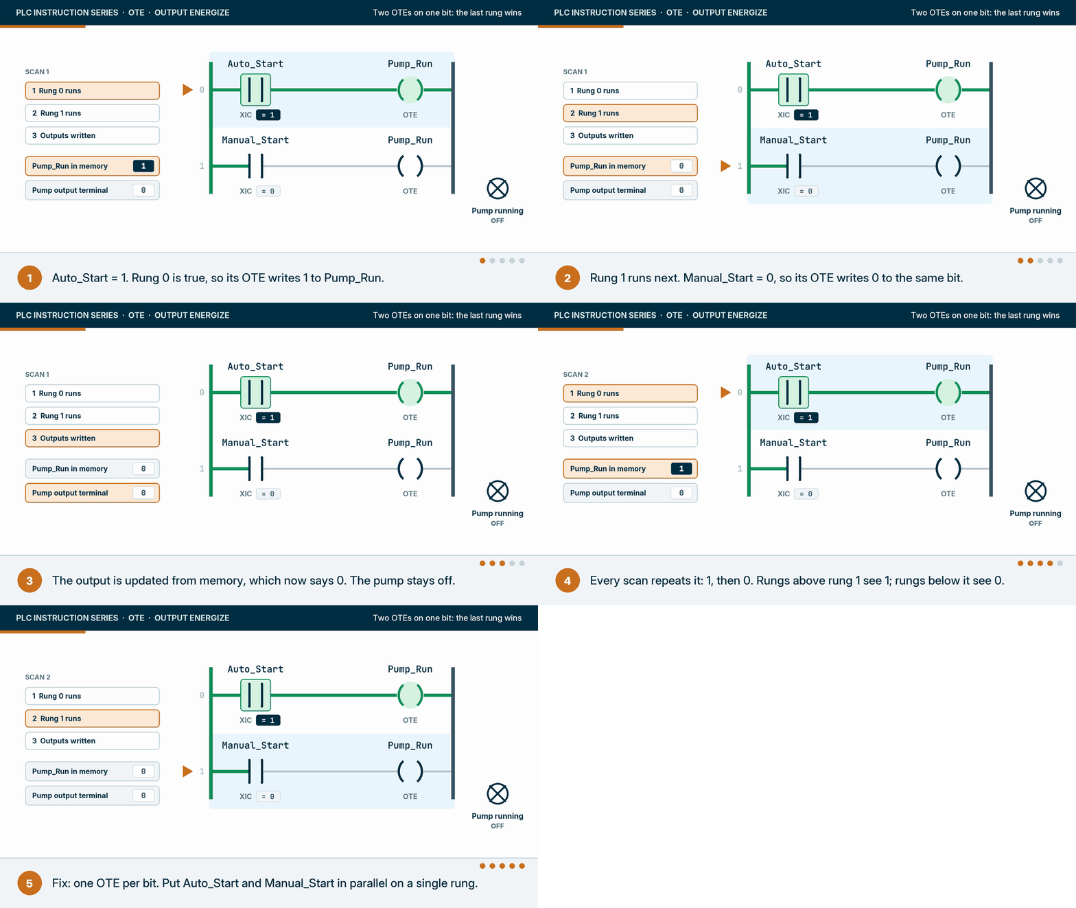
This is the most searched OTE problem, and it comes from treating OTEs as if they ORed together, the way two relay coils on one wire would. They do not. Rockwell does not state “the last one wins” as a rule in the pages we could read; it follows from the execution table, because each OTE writes on every scan. What Rockwell’s SLC 500 manual does say is that using the same address with multiple output instructions is not recommended. Rockwell’s help also describes searching for duplicate destructive bits, which finds OTEs on the same tag; test how your version reports it.
The fix is always the same: one OTE per bit, with every reason to turn the bit on in parallel on its rung.
| Writer on the same bit | What you see | Fix |
|---|---|---|
| A second OTE | The lower rung wins; rungs between them see the other value | Merge the conditions in parallel on one rung |
| An OTL or OTU | The latch is undone the next time the OTE rung is solved | Pick one: either a latch pair or an OTE, never both |
| A MOV or COP on the word the bit lives in | The bit flips whenever the move runs | Keep command bits out of words that are moved as a block |
| An HMI or SCADA write | The button “does nothing”, or flickers for one scan | Give the HMI its own request bit and read it with XIC |
OTE vs OTL: what is the difference?
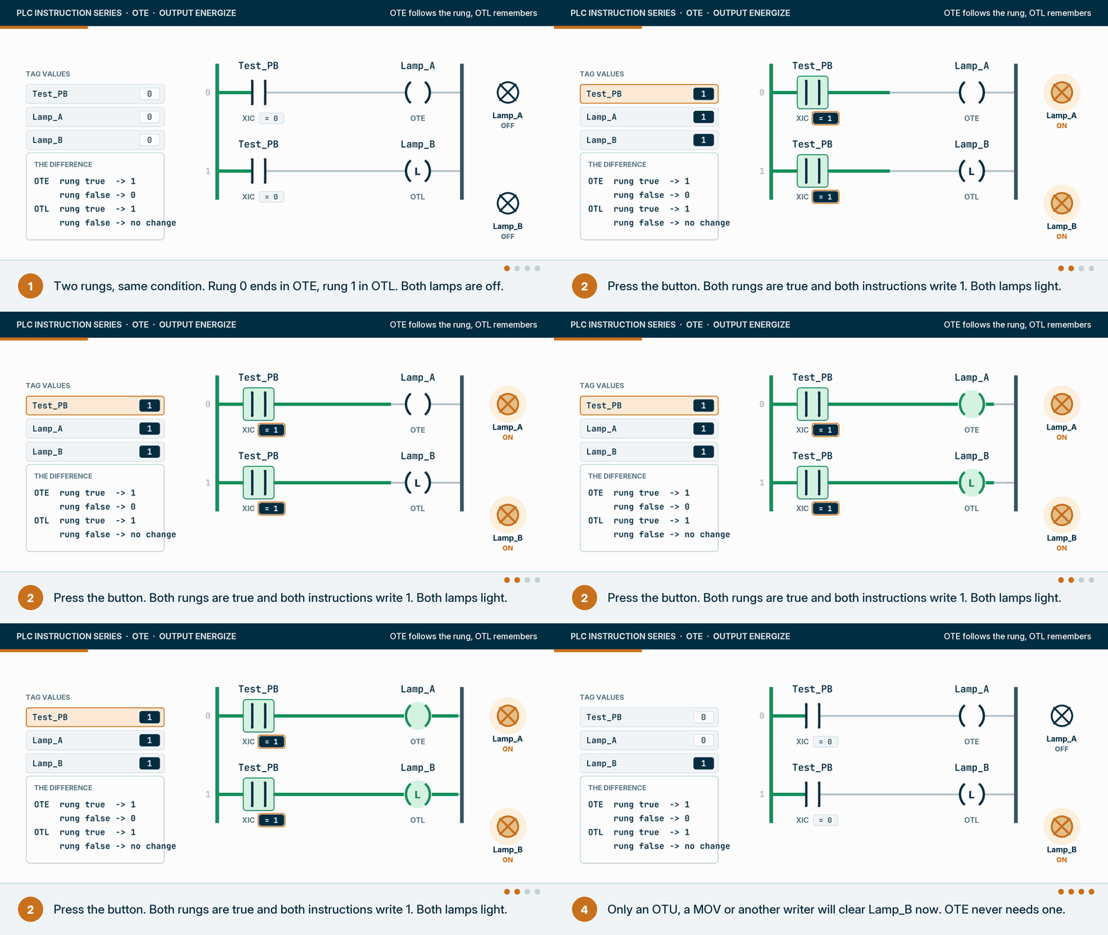
OTE writes 1 when its rung is true and 0 when its rung is false. OTL, Output Latch, writes 1 when its rung is true and does nothing when it is false, so its bit stays 1 until something clears it, usually an OTU. Use OTE for anything that should follow its conditions; use a latch only for state that must outlive them.

| OTE (Output Energize) | OTL (Output Latch) | |
|---|---|---|
| Rung true | Writes 1 | Writes 1 |
| Rung false | Writes 0 | Does nothing |
| Prescan | Clears the bit to 0 | Leaves the bit unchanged |
| Retentive | No | Yes |
| Needs a partner to clear | No | Yes, usually OTU |
| Usual use | Outputs and internal bits that follow their conditions | Faults, sequence flags and memory that must outlast their cause |
Most experienced programmers prefer an OTE with a seal-in branch over an OTL/OTU pair for anything that drives equipment. The seal-in drops out by itself on a stop, a fault or a mode change; the latch has to be cleared deliberately, and forgetting one is how machines restart on their own. The OTL page covers when a latch is the right choice.
How does an OTE behave over time? It rewrites its bit every scan
Because OTE writes its bit every time its rung is solved, nothing else can change that bit for longer than one scan. That is a feature when the OTE owns the bit, and the explanation for a whole family of “it doesn’t work” reports when something else tries to write it.

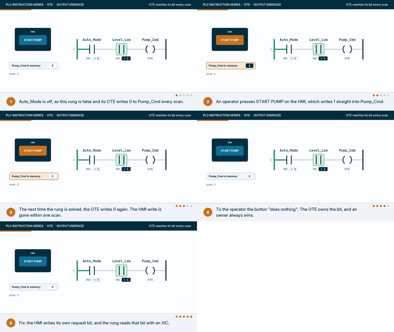
The HMI case is the one that trips up new programmers and integrators alike. An HMI writes tags over the network, outside the scan. If it writes an OTE’s bit, the value survives only until the OTE runs again, a few milliseconds later. The cure is ownership: the HMI writes a request bit, HMI_Pump_Start_Req, that nothing else writes, and the program reads it with an XIC on the OTE’s rung. The same rule applies to recipe downloads, SCADA writes and other controllers.
When does an OTE write? The scan, prescan and output updates
OTE writes its bit at the moment it executes. What reaches the terminal, and when, depends on the controller’s I/O model. And when the controller enters Run mode, every OTE bit is cleared during prescan before the first real scan.

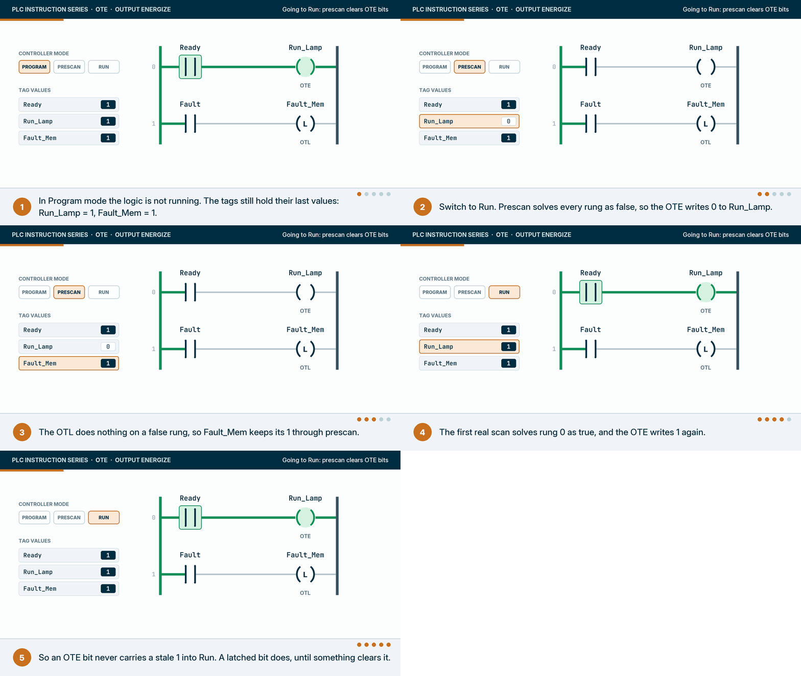
Prescan clears OTE bits
Rockwell’s execution table says prescan clears the OTE bit. That is deliberate: it means no OTE carries a stale 1 into Run. A permissive or an output driven by an OTE starts from 0 and is recalculated on the first scan. Latched bits are different: OTL and OTU do nothing during prescan, so a latched 1 survives the mode change. The SLC 500 manual describes the same reset for OTE bits on entering Run and on power restore.
From the tag to the terminal

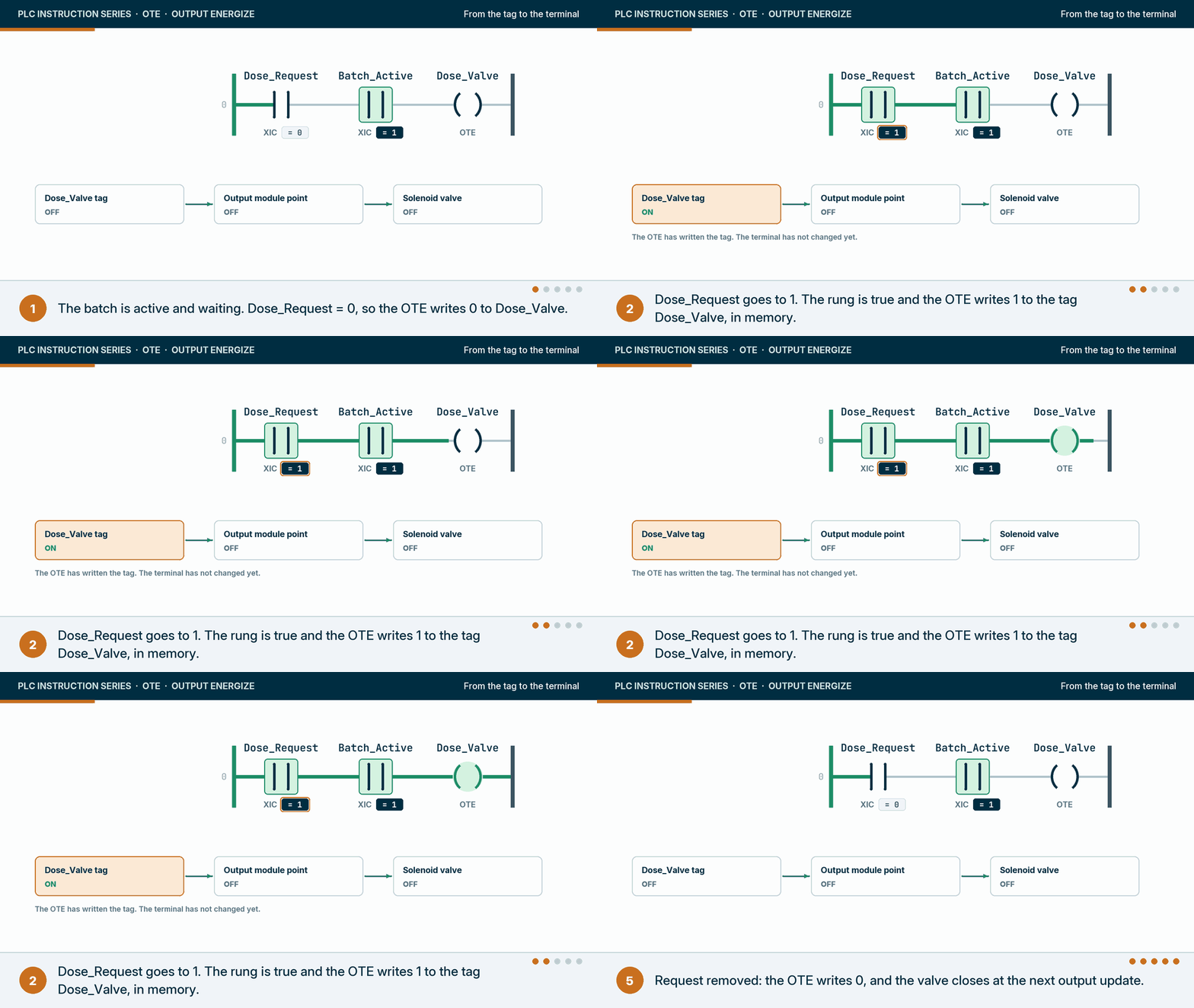
Writing the tag and switching the terminal are two separate events:
- Process image controllers. Siemens documents for the S7-1500 that the process image of the outputs is written to the modules at the end of the cycle. The SLC 500 works the same way, with an output scan after the program scan. Every OTE on an output during the scan ends up as the value written at the end, which is why two duplicate coils produce only the last value at the terminal.
- Logix controllers. ControlLogix and CompactLogix send output data to the modules asynchronously to the program, at each module’s requested packet interval (RPI). An output tag that changes and changes back inside one RPI may never reach the terminal. When an output must change at a precise point in the logic, Logix offers the Immediate Output (IOT) instruction, and the SLC 500 has IOM.
OTE in practice: seven scenarios from simple to advanced
Each scenario shows a rung in a particular state, why OTE is the right instruction, and what goes wrong. Tag names are examples, written the way I would want them in a real program.
1. Packaging: a stack light, one OTE per lamp
A line’s stack light shows green for running, amber for starved and red for faulted. Each lamp is one output, owned by one OTE.

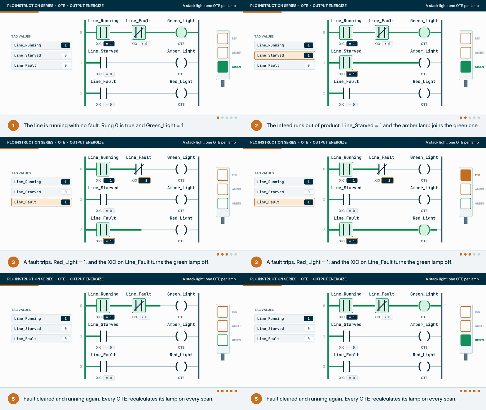
Why OTE: each lamp should follow its condition exactly, on and off, with no memory. What goes wrong: a second rung added years later to “also turn red on for a guard open”. It writes Red_Light with its own OTE, and now red only shows the guard condition, because that rung is lower in the routine. Add the condition to the existing rung instead, in parallel.
2. Packaging: fire the reject gate while a bad pack is at the gate
A checkweigher flags underweight packs, and a tracking bit follows each one down the conveyor. When a flagged pack reaches the reject gate, the gate fires.
Why OTE: the solenoid should be energised only while a flagged pack is at the gate, and drop out the moment it passes. What goes wrong: the pack sits under the gate for only a few scans at line speed. In a Logix controller the output tag can be 1 for less time than the output module’s RPI, so on some configurations the solenoid never fires. Check the input side too: a pulse shorter than the input module’s update interval can be missed before the OTE ever runs. Fixes are a minimum on-time from a timer, an IOT on the output, or a faster RPI, chosen from the actual pack dwell time.
3. Water and wastewater: one OTE per pump, many reasons to call it
A duplex lift station alternates its lead pump. Pump 1 can be called by the level control when it is lead, or by an operator in manual.
Why OTE: P1_Call should be true exactly while one of its reasons is true and pump 1 is healthy. What goes wrong: the tempting version has one rung for the lead call and another for manual, both ending in OTE(P1_Call). Manual then works only when the manual rung happens to be lower in the routine, and then the level call stops working: whichever rung is lower wins, so one of them is always dead, and the station’s behaviour depends on rung order nobody remembers. One owner, all reasons in parallel.
4. Food and beverage: a dosing valve, from the tag to the terminal
A flavour dosing valve opens while a dose is requested and the batch is active. The OTE writes the tag; the valve opens at the next output update.
The tag-to-terminal animation above shows this rung. Why OTE: the valve should be open only while the dose is requested; a request removed for any reason must close it. What goes wrong: dosing by counting scans or by an OTE pulse. A dose measured in scans changes with scan time, and a short pulse may never reach the valve on an asynchronous controller. Dose by a flow meter total or a timer, and let the OTE simply hold the valve open while the dose runs.
5. Pharmaceutical: a cleanroom supply fan and its run command
A cleanroom air handler’s supply fan runs while the unit is enabled and nothing has shut it down.
Why OTE: the run command must disappear the moment any permissive is lost, with no memory. What goes wrong: two things. First, the fire shutdown: stopping fans on smoke is a life-safety function, normally hardwired through the fire alarm system. This rung reads the fire system’s normal relay with an XIC, so a broken wire stops the fan, but the PLC only follows the fire system; it does not perform the shutdown. Second, treating Fan_Run_Cmd as proof the fan is running. The OTE writes what the program wants. In a validated system the room’s pressure cascade depends on the fan actually running, so the program also needs run feedback from the drive or an airflow switch, and an alarm when command and feedback disagree.
6. Automotive: two clamp commands merged into one OTE
A welding fixture clamp can be closed automatically by the sequence or manually from a pushbutton. An earlier version had two rungs, each with its own OTE on Clamp_Close.
Why OTE: the clamp should close while either request is present and a part is in the fixture. What goes wrong: with two OTEs, the manual button only worked while the manual rung was lower than the automatic one, and after someone reordered the routine the manual button stopped working entirely. The merged rung also makes the Part_Present condition apply to both requests, which the old automatic rung had and the manual one did not. And a clamp that closes on a button press is a pinch hazard: the closing action needs its own safeguarding in the safety system, such as two-hand control or a light curtain, not just this OTE.
7. Plastics: a heater zone output that drops on any lost permissive
An extruder barrel zone heater is driven by its temperature control output, and must drop out on a failed thermocouple or an overtemperature.
Why OTE: the heater must turn off the moment any permissive is lost, and turn back on only when all of them return. What goes wrong: the overtemperature limit. A standard OTE that drops the heater is good process control, but the over-temperature protection that prevents a fire belongs to an independent limit controller with its own sensor and contactor. If the PLC’s OTE is the only thing that can turn the heater off, a stuck output or a welded solid-state relay leaves nothing in the way.
What does OTE look like in each vendor’s software?
Every ladder editor has the coil. Rockwell Automation calls it OTE in Studio 5000 Logix Designer and RSLogix 500 (more on those platforms on our Rockwell Automation page). Siemens calls it an assignment; Mitsubishi Electric, CODESYS, Beckhoff and Phoenix Contact call it a coil; AutomationDirect calls it an Out coil. The symbol, a pair of brackets, is the same everywhere.
| Vendor | Software | Name of the instruction | Example operand | Text form |
|---|---|---|---|---|
| Rockwell Automation | Studio 5000 Logix Designer | OTE, Output Energize | Pump_Run, Local:2:O.Data.0 | Rung text OTE(Pump_Run); ST Pump_Run [:=] expr; |
| Rockwell Automation | RSLogix 500 (SLC 500, MicroLogix) | OTE, Output Energize | O:2/0, B3:1/4 | OTE O:2/0 |
| Siemens | TIA Portal (S7-1200, S7-1500) | Assignment | "Pump_Run", %Q0.0 | STL = "Pump_Run" on S7-1500 |
| Mitsubishi Electric | GX Works3 (MELSEC iQ-R) | Coil | Y20, M100 | OUT Y20 |
| IEC 61131-3 / CODESYS, Beckhoff | CODESYS, TwinCAT 3 | Coil | A named BOOL variable | ST bPumpRun := expr; |
| Phoenix Contact | PLCnext Engineer | Coil | A named BOOL variable | ST assignment |
| AutomationDirect | CLICK Programming Software | Out coil | Y001, C10 | None; ladder only |
Sources: Rockwell Automation 1756-RM003 and 1747-RM001; Siemens TIA Portal V20 help (LAD and STL for S7-1500); Mitsubishi Electric SH(NA)-081265ENG; CODESYS and Beckhoff online help; Phoenix Contact PLCnext Engineer help; AutomationDirect CLICK instruction list.
The same OTE in each vendor’s editor
These are real screenshots of the output coil in 26 programming environments, ordered as on the XIC page: the platforms that dominate North American plants first, then the machine-builder platforms, then compact and regional controllers. Each one is framed the same way, with the coil ringed in amber and the source credited under it. Pick a tab to switch software.
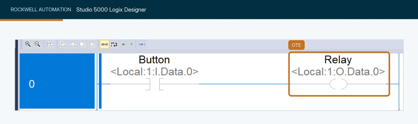
Relay (Local:1:O.Data.0), driven by an XIC on Button (Local:1:I.Data.0). The OTE follows the rung condition each scan. Screenshot: Control.com, Intro to PLC Programming with Rockwell's Studio 5000 and CompactLogix.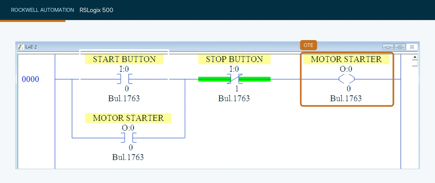
O:0/0 (MOTOR STARTER) at the right end of the rung, energised when the start and stop conditions are true. RSLogix 500 drew the OTE as a round-bracket coil. Screenshot: SolisPLC, PLC Programming Fundamentals: OTE Output Energize Instruction.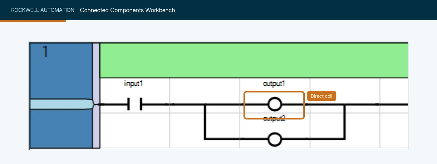
output1, in parallel with a second direct coil output2, driven by the contact input1. A direct coil follows its rung each scan. Screenshot: Rockwell Automation, Micro800 Programmable Controllers General Instructions.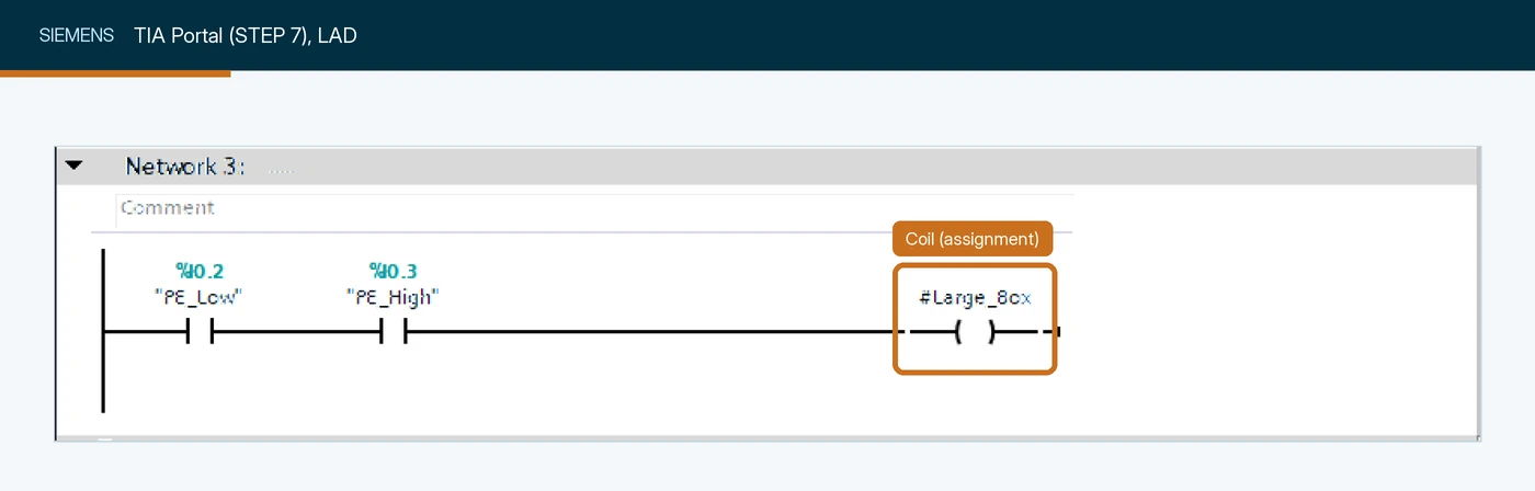
#Large_Box, driven by two normally open contacts "PE_Low" (%I0.2) and "PE_High" (%I0.3) in series. Siemens calls the output coil "Assignment". Screenshot: SolisPLC, An Introduction to Basic Ladder Logic Instructions in Siemens TIA Portal.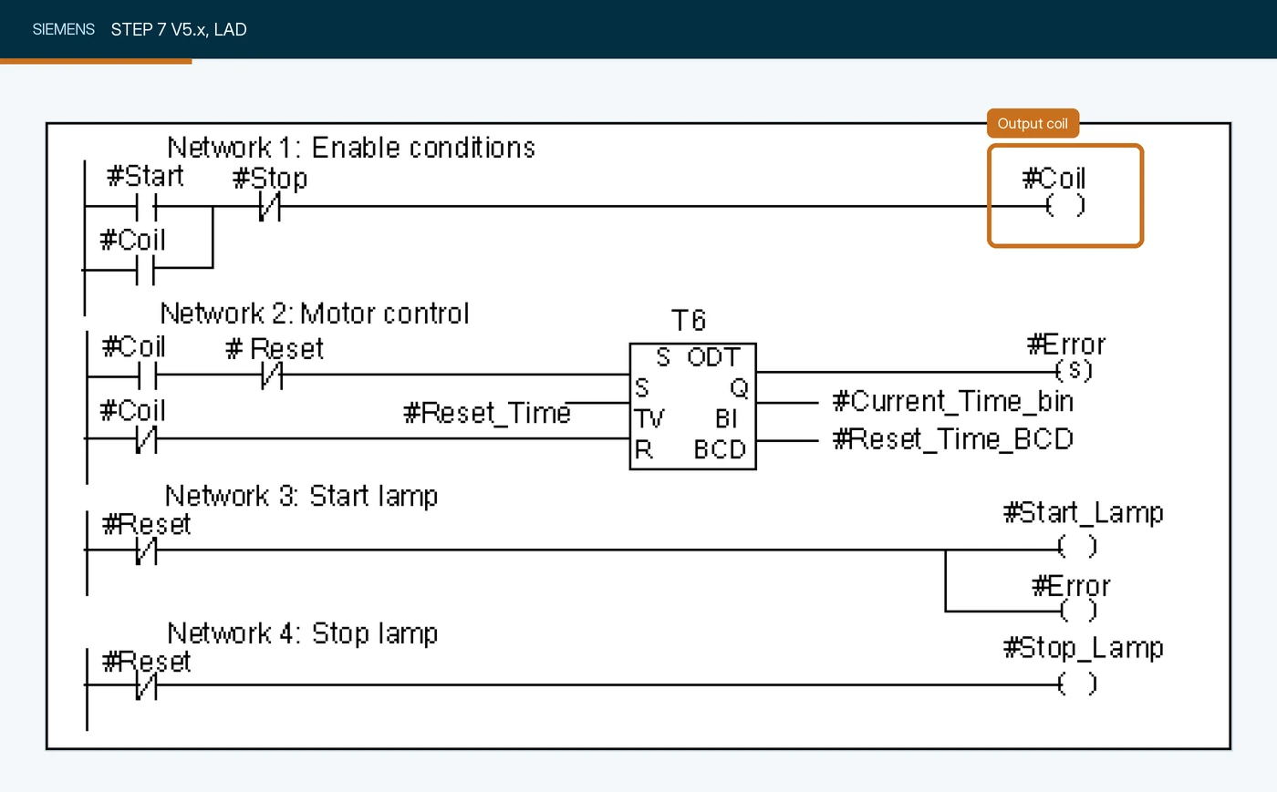
-( )- on #Coil at the right end of Network 1, driven by #Start and #Stop contacts. The Classic editor draws it as a plain coil. Screenshot: Siemens AG, Programming with STEP 7.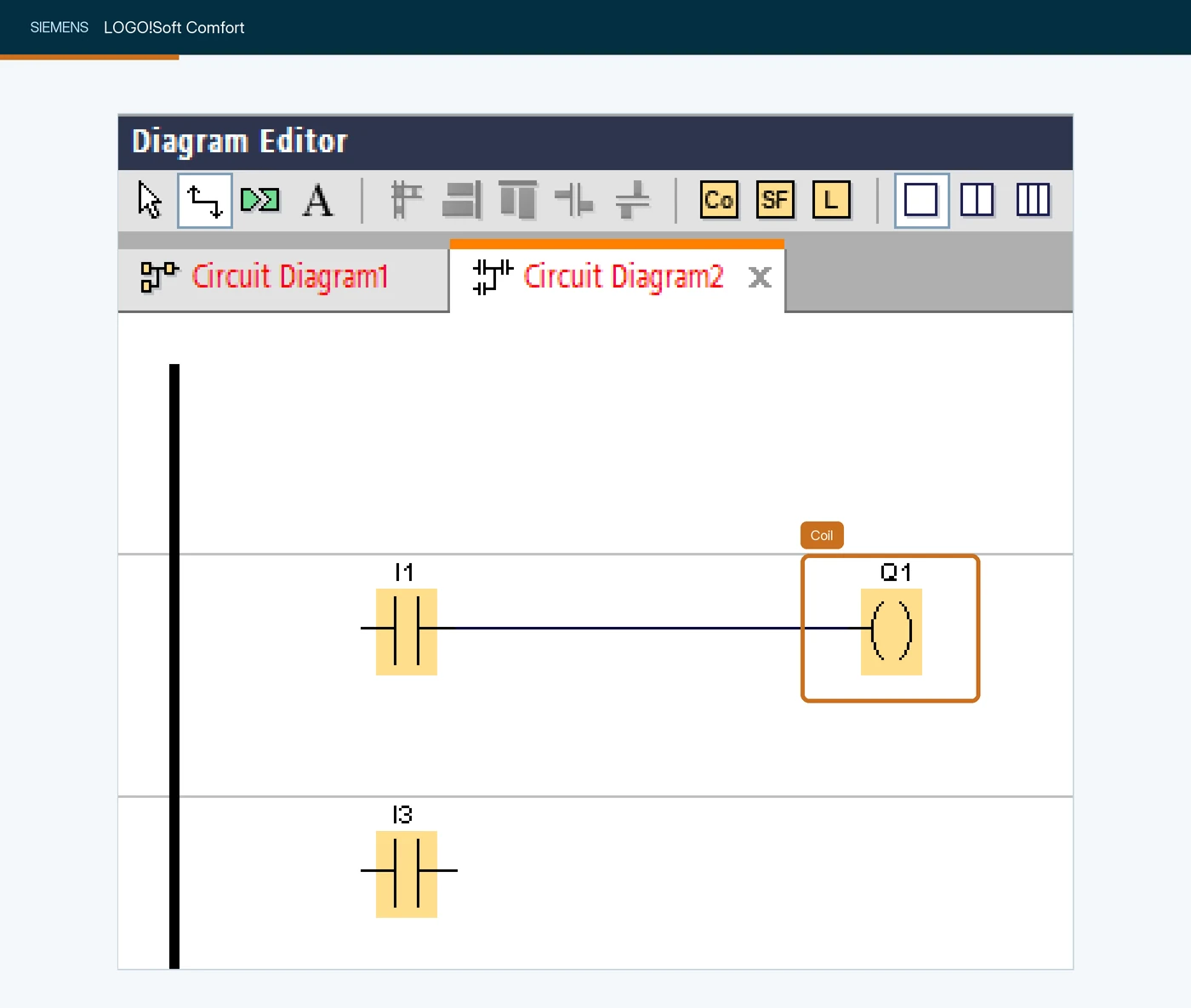
Q1, wired to the contact I1. LOGO! calls it a coil (Co) and it drives output Q1. Screenshot: SolisPLC, Siemens LOGO PLC Training: How to Get Started with LOGO!Soft Comfort.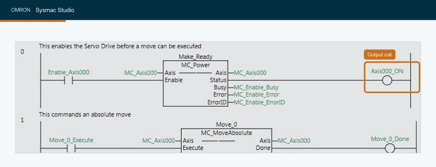
Axis000_ON at the end of rung 0, enabled by Enable_Axis000 through an MC_Power function block. Sysmac operands are named variables. Screenshot: Omron Europe, Using 3D simulation in Sysmac Studio (Automation Knowledge Base).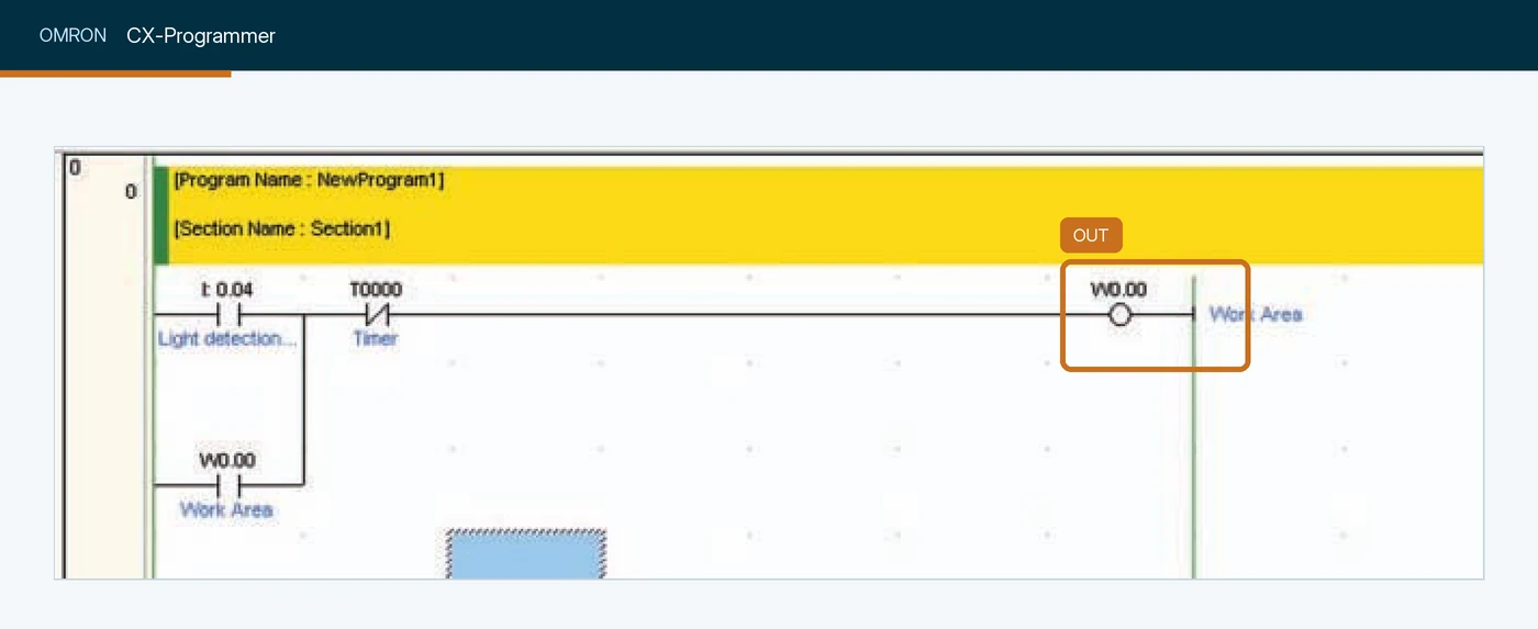
W0.00 ("Work Area"), driven by I 0.04 and a normally closed T0000. OUT writes the rung result to the bit every scan. Screenshot: Omron, CP1L/CP1E CPU Unit Introduction Manual (W461).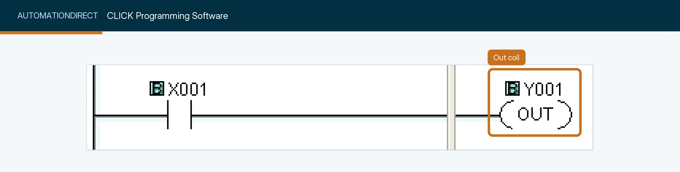
Y001, energized whenever the contact on X001 passes power. Screenshot: AutomationDirect, CLICK help, Out Coil.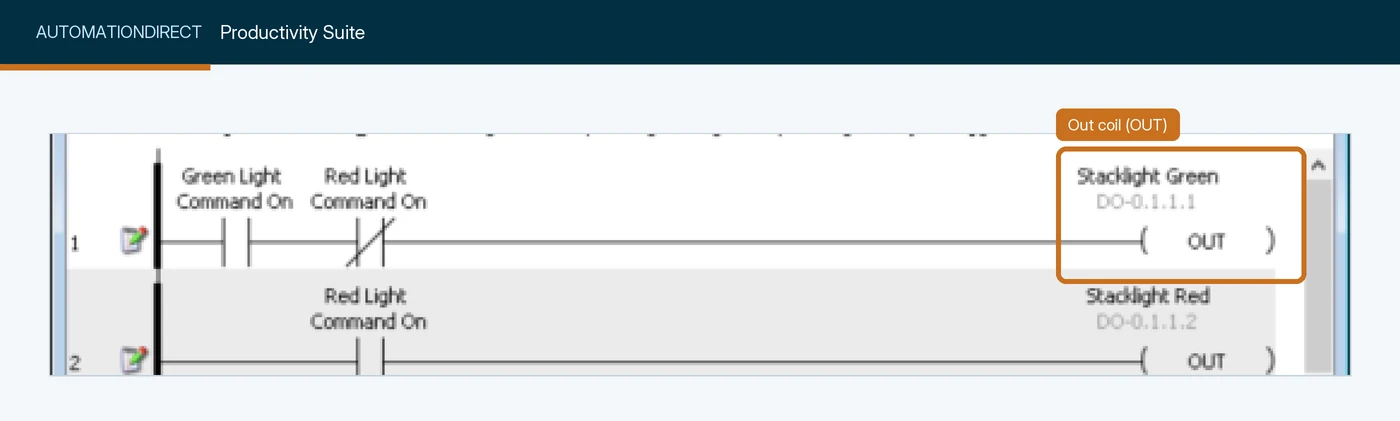
OUT) on the "Stacklight Green" output at the right edge of rung 1. Screenshot: AutomationDirect, Productivity Suite help, Ladder Editor Window.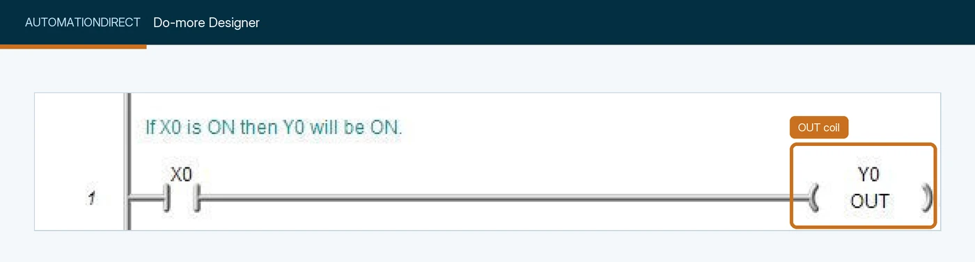
OUT coil on output Y0, driven by a normally open contact on X0. Screenshot: AutomationDirect, Do-more Designer help, OUT - Output Coil.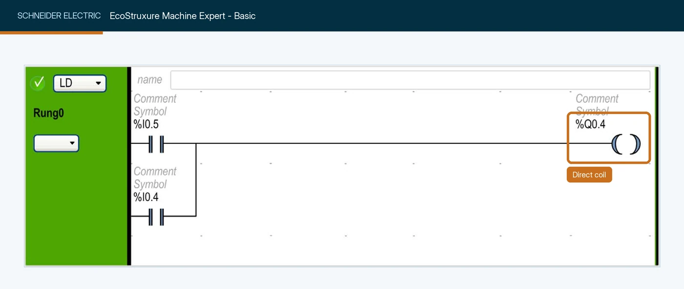
%Q0.4, driven by two parallel contacts. Screenshot: Schneider Electric, EcoStruxure Machine Expert - Basic, Operating Guide (EIO0000003281).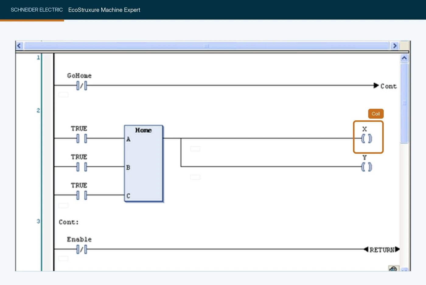
X, fed from a function block output. Screenshot: Schneider Electric, Machine Expert help, Working in the FBD and LD Editor.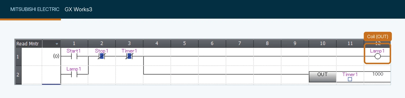
Lamp1, shown in monitor mode with its seal-in contact below. Screenshot: Mitsubishi Electric, FX5U Training Manual.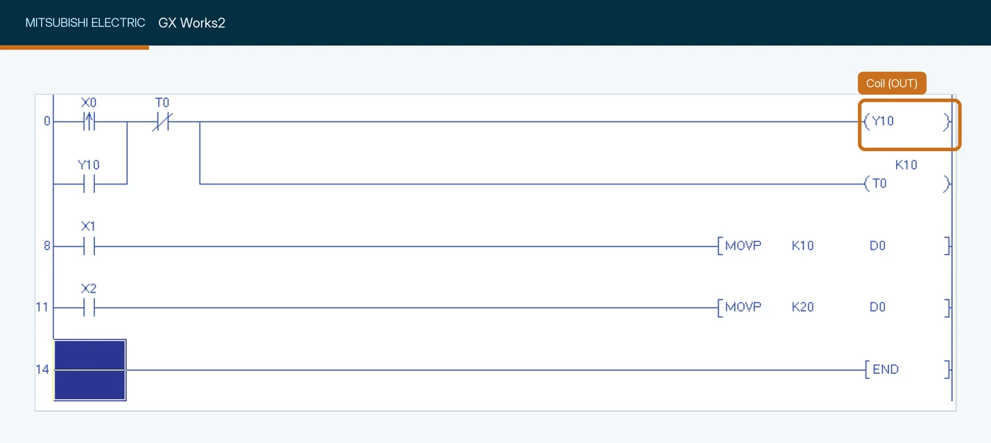
Y10, shown in the converted ladder of the beginner project. Screenshot: Mitsubishi Electric, GX Works2 Beginner's Manual (Simple Project).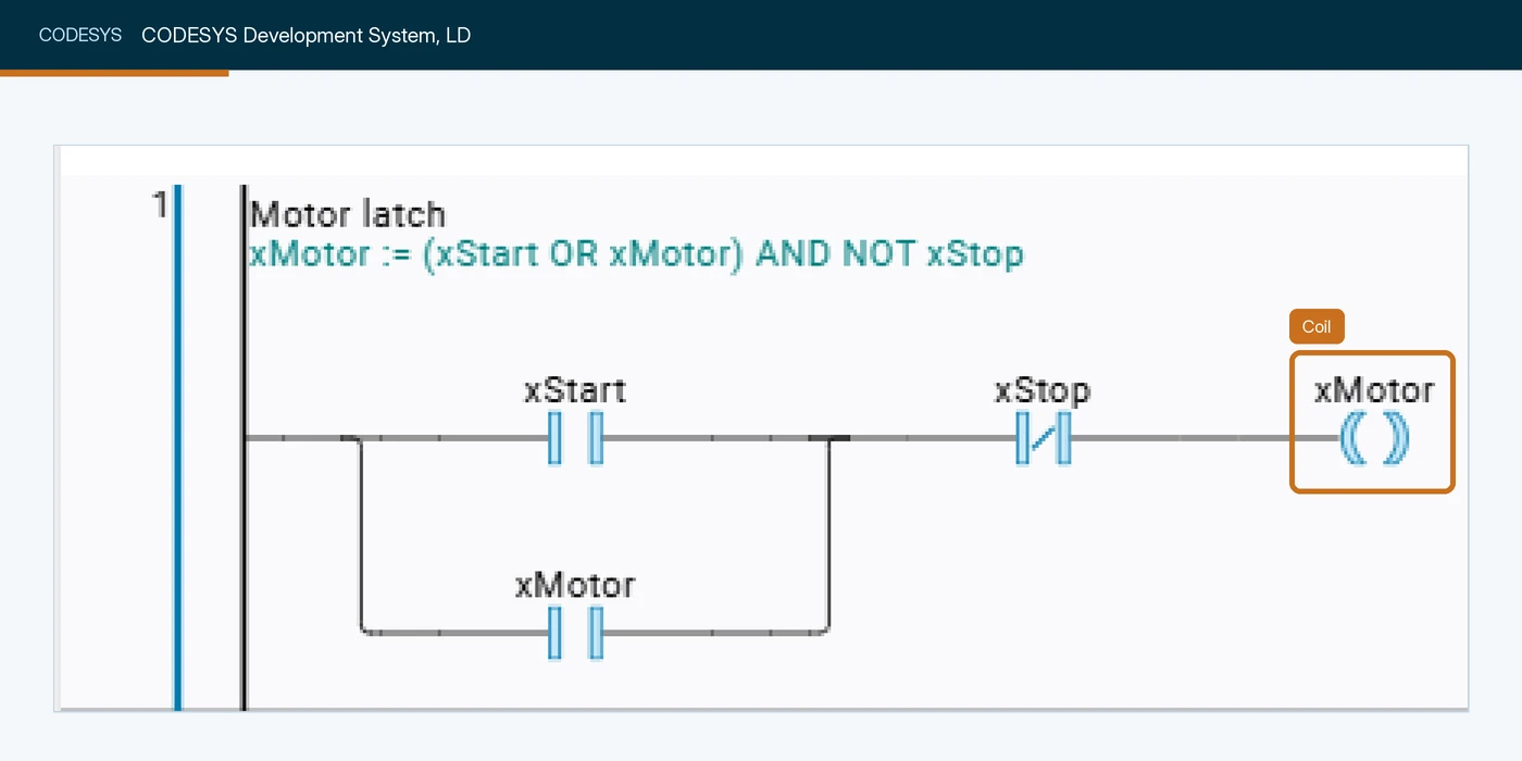
xMotor, driven by a start/stop circuit with seal-in. Screenshot: CODESYS Group, CODESYS 4 online help, Binary circuits.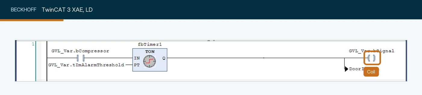
GVL_Var.bSignal, driven by the output of a TON timer. Screenshot: Beckhoff Automation, Your first TwinCAT 3 PLC project.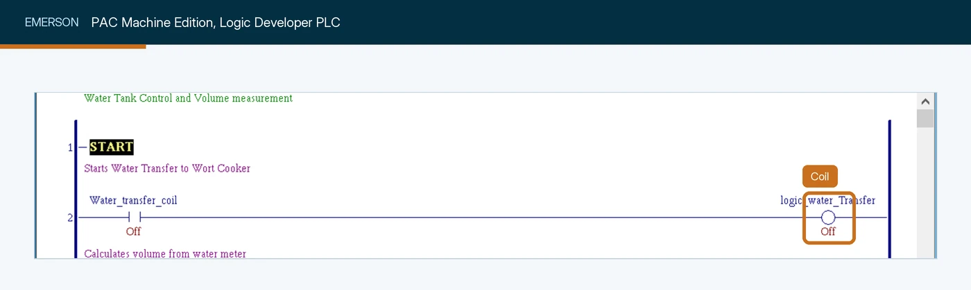
logic_water_Transfer, monitored, so its current value (Off) is shown under it. Screenshot: Emerson, PAC Machine Edition Logic Developer - PLC Getting Started Guide (GFK-1918AB).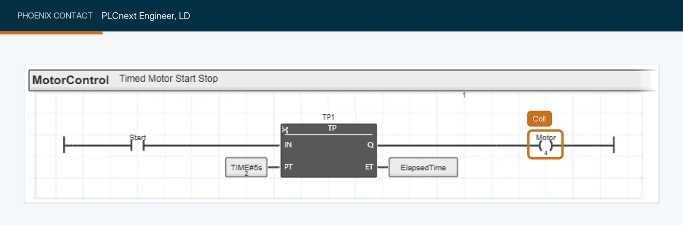
Motor, driven by the output of a TP timer. Screenshot: Phoenix Contact, PLCnext Engineer online help: Editing LD Networks.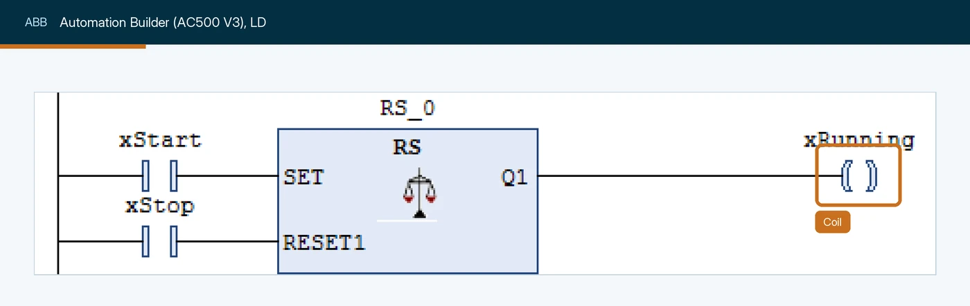
xRunning, driven by the output of an RS bistable block. Screenshot: ABB, AC500 V3 PLC - Bistable, Counter, Timer & Trigger (Technical Note 12).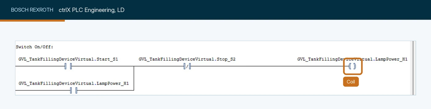
LampPower_H1, at the end of a network with Start_S1 and Stop_S2. Screenshot: Bosch Rexroth community, How to run a ladder diagram simulation using ctrlX PLC 1.20.7 (forum post).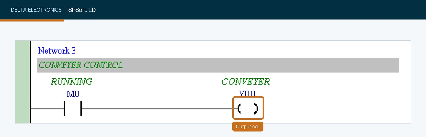
Y0.0, driven by a single contact on M0. Screenshot: Delta Electronics, ISPSoft User Manual.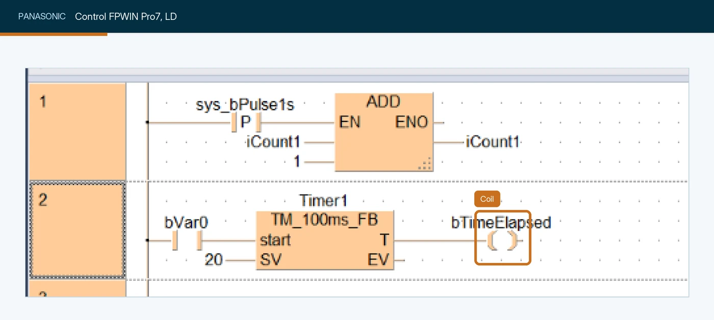
bTimeElapsed, driven by the output of a TM_100ms_FB timer. Screenshot: Panasonic Industry, Control FPWIN Pro7 help: Add contacts and a coil.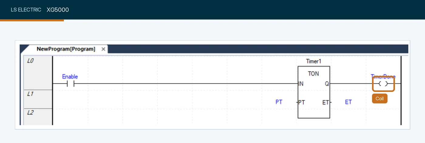
TimerDone, driven by the output of a TON timer. Screenshot: LS Electric, XG5000 help (hosted by AutomationDirect): Ladder.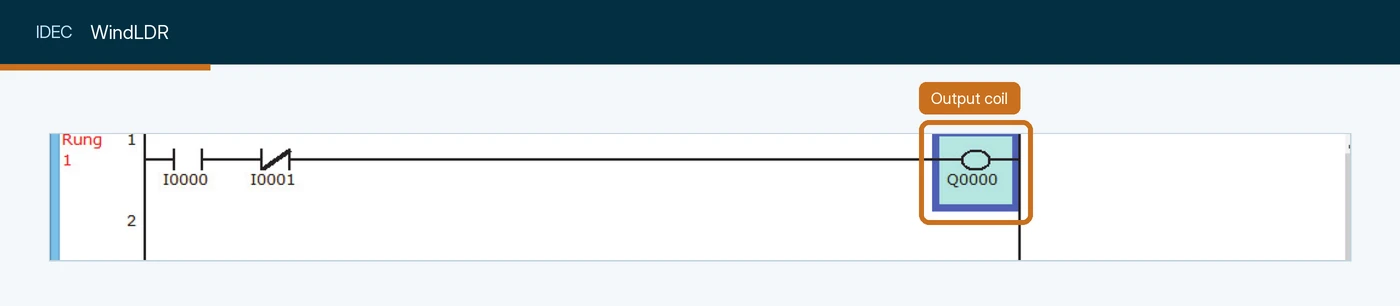
Q0000, selected in the editor (blue frame is the software's own selection). Screenshot: IDEC Corporation, FC6A Series MicroSmart LAD Programming Manual (FC9Y-B1726).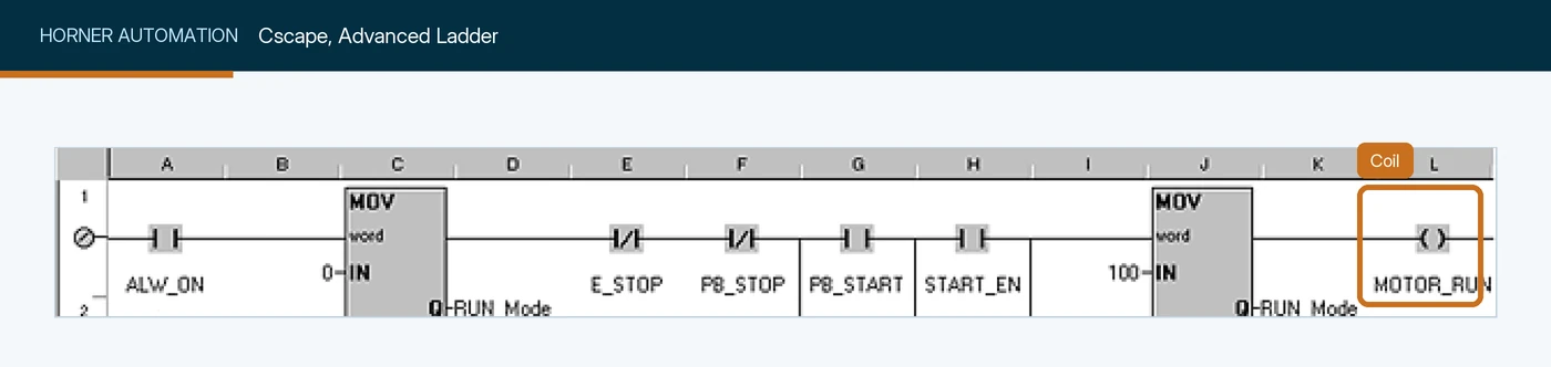
MOTOR_RUN, at the end of a rung of contacts and function blocks. Screenshot: Horner Automation Group, Cscape help: Contacts and Coils in Advanced Ladder.| Vendor | Software | Why it is not shown yet |
|---|---|---|
| Schneider Electric | EcoStruxure Control Expert (Modicon M340, M580) | The manual’s LD chapter shows only drawn symbols, with no editor window. Machine Expert and Machine Expert - Basic are shown above. |
| KEYENCE | KV STUDIO | The manuals sit behind a download form and no public screenshot of the ladder editor turned up. |
| B&R | Automation Studio | No public screenshot of the LD editor. |
| Inovance | InoProShop, AutoShop | The public manuals have no ladder editor figures. |
| WAGO | e!COCKPIT | No public LD screenshot; it is built on CODESYS, shown above. |
If you work in one of these, the instruction is the same coil; we will add your editor when we capture it ourselves.
Three differences matter when you switch platforms. Siemens’ assignment writes the result of logic operation (RLO) to its operand and does not change the RLO, so in LAD and FBD several assignments can hang off one network. CODESYS and Beckhoff only allow several coils in one network in parallel. And Mitsubishi Electric’s GX Works3 has a duplicated-coil check; its own FAQ notes that SET and RST on one device are not flagged. If you want a practice environment, I have walked through installing RSLogix 500 for free and TIA Portal.
Why won’t my OTE turn on (or off)? A debugging checklist
When an OTE’s bit or its output is not doing what the rung says, the rung is usually right and something around it is not. Work from the rung out to the terminal.
- Check the rung condition at the coil. Online, the coil shows the rung condition reaching it. If the coil is false, debug the inputs, not the output.
- Cross-reference the bit. Look for every writer: other OTEs, OTL and OTU, MOV and COP on the containing word, HMI and SCADA tags. More than one writer explains almost every “it turns on and off by itself” report.
- Check whether the routine is being scanned. An OTE in a routine that no JSR calls, or in an inhibited task, freezes at its last value.
- Check the MCR zone and SFC step. An OTE in a false MCR zone is cleared (Rockwell’s MCR help). In an SFC non-stored action the output is normally cleared when the step ends; confirm it in the SFC manual and check the action qualifier.
- Follow the output tag to the module. Confirm the alias points at the right point, the module is not faulted, and its connection is running. A faulted output module holds its outputs in the state its fault configuration says (the Fault Mode setting on the module), not the tag’s value.
- Check the output indicator and the field. If the module’s point indicator follows the tag but the device does not move, the problem is outside the controller: the fuse, the wiring, the interposing relay or the device.
- Look for forces. A forced output holds its value whatever the OTE writes.
- Think about pulse length. On Logix, a tag that is 1 for less than the module’s RPI may never reach the terminal.
Steps 2 and 3 find most problems, and both are much easier in a program with a written standard and version control for PLC code.
Common OTE mistakes
| Mistake | What happens | Fix |
|---|---|---|
| Two OTEs on the same bit | The lower rung wins; behaviour depends on rung order | One OTE per bit, all conditions in parallel |
| HMI writes directly to an OTE bit | The button does nothing or works for one scan | HMI writes its own request bit; read it with XIC |
| Expecting OTE to hold its bit | The output drops as soon as the condition goes | Seal-in branch, or a latch pair for true memory |
| OTE and OTL on the same bit | The latch is undone every scan by the OTE | Choose one approach for each bit |
| Reading the command as feedback | The program trusts what it asked for | Separate feedback input and a discrepancy alarm |
| OTE in a subroutine that stops being called | The bit freezes at its last value | Clear the bits when the subroutine is skipped, or call it every scan |
| Standard OTE as the safety output | Safety depends on standard logic and a standard output | Safety relay or safety controller with safety-rated outputs |
Test yourself: an interview quiz on OTE
Ten questions, the kind I'd ask in an interview for a controls role to see whether someone really understands OTE. Pick an answer and the explanation appears straight away.
0 of 10 answered
What does an OTE write when its rung is false?
Rockwell's execution table clears the OTE bit whenever the rung condition is false. OTE makes its bit equal to the rung on every execution; it is not a latch.
What happens to an OTE bit during prescan, when the controller enters Run?
The execution table clears the bit in prescan and postscan. That is why an OTE never carries a stale 1 into Run, unlike a latched bit.
Rung 5 ends in OTE(Pump_Run) and is true. Rung 30 ends in OTE(Pump_Run) and is false. What value does the Pump_Run tag hold at the end of the scan?
Each OTE writes the bit when it executes, so the last one to execute in the scan sets the final value. OTEs do not OR together.
In the same program, what value of Pump_Run does an XIC on rung 20 see?
Rung 20 runs after rung 5 and before rung 30, so it sees the 1 that rung 5 just wrote. Duplicate coils make one bit mean different things in different parts of the program.
An HMI writes 1 to a bit that an OTE on a false rung owns. How long does the 1 last?
The OTE rewrites its bit every time its rung is solved. Give the HMI its own request bit and read it with an XIC.
What is the difference between OTE and OTL when the rung goes false?
OTL only ever writes 1, and only when its rung is true. That is what makes it retentive and why it needs an OTU or another writer to clear it.
A JSR stops calling a subroutine. What happens to an OTE inside it that was writing 1?
An OTE only writes when it executes. Rockwell's SLC 500 manual notes that a bit set in a subroutine stays set until the subroutine is scanned again.
On a ControlLogix controller, when does an output terminal change after an OTE writes its tag?
Logix sends output data to modules asynchronously to logic execution, at each module's requested packet interval. A tag pulse shorter than the RPI may never reach the terminal.
What does Siemens TIA Portal call the OTE equivalent in LAD?
Siemens calls it an assignment: it writes the result of logic operation to its operand. In STL on the S7-1500 it is the equals sign.
Which is the best fix for two rungs that both end in OTE(Clamp_Close)?
One owner per bit. Merging the conditions removes the dependence on rung order and keeps every reason to close the clamp in one place.
That's the basics covered. If you'd like the next instruction in this guide in your inbox, the sign-up is below. It's never needed to see an answer.
Five harder OTE problems
These are commissioning-grade problems. Try each on paper before opening the solution. The rungs are written in Logix rung text: XIC(tag) and XIO(tag) are contacts, square brackets with commas are parallel branches, and OTE(tag) is the output coil.
Problem 1: the pump that runs in auto but not in hand
A pump has these two rungs. The hand rung is near the top of the routine; the auto rung was added later, 40 rungs below it:
XIC(Hand_Mode) XIC(Hand_Start_PB) OTE(P101_Run);
XIC(Auto_Mode) XIC(Level_High) OTE(P101_Run);
In auto the pump works. In hand, pressing Start does nothing. Explain, then rewrite.
Show the solution
Both rungs own P101_Run. In hand, the hand rung is true and writes 1. Forty rungs later the auto rung runs; it is false because Auto_Mode is 0, and an OTE on a false rung writes 0. The bit ends every scan at 0, so the output never turns on. In auto the problem is invisible, because the auto rung is the last writer and it is the one that matters.
One owner, both modes in parallel:
[XIC(Auto_Mode) XIC(Level_High) ,XIC(Hand_Mode) XIC(Hand_Start_PB) ] XIO(P101_Fault) OTE(P101_Run);Adding the fault on the shared path also fixes a second bug: in the old version neither rung checked the pump fault. A real pump rung would also seal in the hand start with a stop, and use a high and a low level for auto so the pump does not chatter; they are left out to keep the point.
Problem 2: a reject solenoid that misses packs at high speed
On a ControlLogix line, XIC(Reject_Tracked) XIC(Pack_At_Gate) OTE(Reject_Sol) drives a solenoid on a 1756 output module with an RPI of 20 ms. The continuous task scans in 6 ms. At full line speed a pack sits under the gate sensor for about 15 ms, and roughly one bad pack in ten is not rejected. Explain, and give two fixes.
Show the solution
The OTE writes the output tag correctly for the two or three scans the pack is under the sensor, but Logix sends output data to the module at its RPI, asynchronously to the scan. A 15 ms pulse on a tag that is sent every 20 ms can fall entirely between two updates, so the module never sees it.
Fix one: stretch the command so it is always longer than the update interval, for example with an off-delay timer that holds the solenoid on for 60 ms after the pack is seen, chosen from the gate’s mechanical response. Fix two: reduce the module’s RPI, or add an IOT for the output on the rung so the data is sent immediately. Often both: a defined minimum on-time is good mechanical practice anyway. Then prove it with the line at full speed and a count of rejected versus flagged packs.
Problem 3: the HMI start that only works sometimes
An HMI start button writes 1 to Mixer_Start. The program has XIC(Mixer_Start) XIC(Mixer_Ready) OTE(Mixer_Run) near the top of the routine and, near the end, XIC(Mixer_Run) OTE(Mixer_Start), added “to clear the start request once the mixer is running”. Operators say the button only works sometimes. Explain and fix.
Show the solution
Mixer_Start has two writers: the HMI and an OTE. The OTE writes it on every scan, true or false. While the mixer is stopped, that rung is false, so it writes 0 to Mixer_Start near the end of every scan. The HMI writes over the network, outside the scan, so its 1 lands at a random point in the scan. If it lands after the clear rung and before the mixer rung of the next scan, the mixer rung sees it and the mixer starts. If it lands anywhere else, the clear rung writes 0 over it before the mixer rung ever reads it. The button works when the timing happens to suit it.
Let the HMI own its request bit and let the program own the run bit:
XIC(Mixer_Ready) XIO(Mixer_Stop_Req) [XIC(HMI_Mixer_Start) ,XIC(Mixer_Run) ] OTE(Mixer_Run);The HMI writes HMI_Mixer_Start as a momentary button and nothing in the program writes it. The seal-in on Mixer_Run keeps the mixer running after the button is released, and losing Mixer_Ready or a stop request drops it. Delete the clear rung: an OTE that writes 0 whenever it is false is not a clear, it is a second owner. And if the HMI button could ever stick at 1, put a one-shot (ONS) on HMI_Mixer_Start so a stuck request cannot restart the mixer by itself when Mixer_Ready returns.
Problem 4: a subroutine output that will not turn off
A packaging machine calls the routine Glue_Control with XIC(Glue_Enabled) JSR(Glue_Control, 0). Inside it, XIC(Glue_Demand) OTE(Glue_Valve) drives the glue valve. When an operator disables glue with Glue_Enabled, the valve sometimes stays open and floods the flaps. Explain, and fix it two ways.
Show the solution
When Glue_Enabled goes to 0, the JSR stops calling the subroutine, so the OTE inside it is never executed again. An OTE only writes when it runs; one that is not scanned keeps its last value. If the valve was open when glue was disabled, it stays open. Rockwell’s SLC 500 manual describes exactly this: a bit set in a subroutine stays set until the subroutine is scanned again.
Fix one: call the routine every scan and put XIC(Glue_Enabled) on the valve rung inside it, so the OTE always runs and writes 0 when glue is off. Fix two: keep the conditional call but clear the subroutine’s outputs when it is skipped, for example with XIO(Glue_Enabled) OTU(Glue_Valve) in the calling routine (a deliberate exception to the one-owner rule: the two never run in the same scan). Fix one is clearer and is what I would choose.
Problem 5: the stack light that ignores the guard
A colleague added guard monitoring to an existing machine. The stack light rung near the top of the routine is XIC(Line_Fault) OTE(Red_Light). The new rung, at the bottom, is XIC(Guard_Open) OTE(Red_Light). During testing, red comes on for an open guard but not for a line fault. Explain why, and write the correct rung.
Show the solution
Two OTEs own Red_Light. The guard rung is lower, so its value is the one the output receives: 1 when the guard is open, 0 otherwise. When a line fault occurs with the guard closed, the first rung writes 1 and the guard rung overwrites it with 0 before the outputs are updated. The light never shows the fault.
[XIC(Line_Fault) ,XIC(Guard_Open) ] OTE(Red_Light);One owner, both reasons in parallel, and delete the second rung. Then run a cross reference on every output the change touched. A guard monitoring signal shown on a stack light is status for the operator; the guard’s protective function belongs to the safety system.
Keep learning between pages
Sign up for The Plant-Side Brief, Joltek's free weekly email for controls engineers and technicians. Every answer on this page stays open whether you sign up or not.
Where OTE fits in this guide
OTE is the third instruction in Joltek’s PLC Programming guide, after the input contacts XIC and XIO. With those three you can build most of the rungs in a machine program. The next pages cover the two other output instructions, OTL and OTU, then the one-shot, timers and counters. The instruction glossary lists them all.
If your team needs this kind of grounding on its own equipment and programs, that is what our hands-on PLC and SCADA training for plant teams is for.
References and further reading
- Logix 5000 Controllers General Instructions Reference Manual (1756-RM003) · Rockwell AutomationOutput Energize (OTE): operand, execution table including prescan and postscan clearing. Read in revision P (December 2014).
- SLC 500 Instruction Set Reference Manual (1747-RM001) · Rockwell AutomationOTE reset on entering Run, on power restore and in a false MCR zone; multiple output instructions on one address not recommended.
- LAD (S7-1200, S7-1500): Assignment · Siemens, TIA Portal V20 online help
- MELSEC iQ-R Programming Manual (Program Design), SH(NA)-081265ENG · Mitsubishi ElectricCoil, inverse coil, set and reset coils.
- CODESYS LD/FBD: Coil · CODESYS Group, online help
- SIMATIC S7-1500 Cycle and Response Times, Function Manual · SiemensThe process image of the outputs is written to the modules at the end of the cycle.
- ControlLogix 5590 Controllers User Manual: Determine When I/O Data Is Updated (1756-UM900) · Rockwell AutomationI/O data is refreshed asynchronously to logic execution.